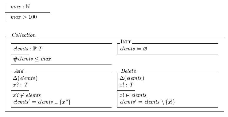
In this example, the class has one attribute elemts denoting a set of elements of the predefined type T. The class invariant stipulates that the size of the set cannot exceed the constant number max. An initialized collection contains no elements (i.e. elemts is the empty set).
Operation schemas have a D-list of those attributes whose values may change. By convention, no D-list means no attribute changes value. Every operation schema implicitly includes the state schema in un-primed form (the state before the operation) and primed form (the state after the operation). Hence the class invariant holds at all times: in each possible initial state and before and after each operation.
In this example, operation Add adds a given input x? to the existing set provided the set has not already reached its maximum size (an identifier ending in '?' denotes an input). Operation Delete outputs a value x! defined as one element of elemts and reduces elemts by deleting x! from the original set (an identifier ending in '!' denotes an output).
2.2 Inheritance
Inheritance is a mechanism for incremental specification, whereby new classes may be derived from one or more existing classes.
Essentially, all definitions are pooled with the following provisions. Inherited type and constant definitions and those declared in the derived class are merged. The state and initialization schemas of derived classes and those declared in the derived class are conjoined. Operation schemas with the same name are also conjoined.
Inheritance in Object-Z can be used to define a new class by extending an existing class. For instance, the class DAG denoting a directed acyclic graph can be defined by inheriting Collection with renaming of the attribute elemts to nodes.
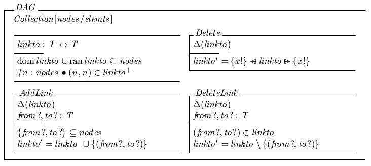
The class DAG inherits the state variable elemts (renamed to nodes) and the operation Add from Collection. It also includes explicitly the state variable linkto denoting the links between members of nodes and the extra operations AddLink and DeleteLink. The operation Delete for DAG is defined as the conjunction of the operation Delete inherited from Collection and the operation Delete declared explicitly in DAG. The expanded version of DAG is as:
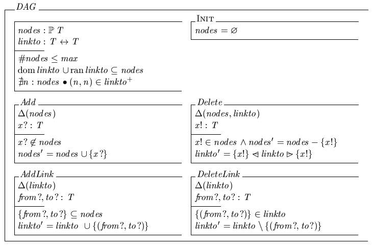
It's necessary to view a full expanded version of an inheriting class, perhaps for the purpose of reasoning a class in isolation. It is desirable to have a case tool to automatically support the inheritance zoom-in/out feature.
3. Formal Models of the Web Environment and Projections
Now, let's start with the formal design of what we are going to build. The construction of a formal model of the Object-Z web environment and projection tools must start with the formalizing the related Object-Z syntax definitions. The typing and dynamic semantics issues are not related since the web environment only concerns some syntax checks. Therefore, the static and dynamic semantics of Object-Z were deliberately left out in the following model.
3.1 Formal model of the web environment
Firstly, the character sets are defined by the Z free type definition as:
- Char ::= 'a' | 'b' | ... | '1' | '2' | ... | ':' | '/' | '#' | ...
The string type is defined as a sequence of characters:
- String == seq Char
At the syntactic level, a type constructor and a type are similar which are modelled as:
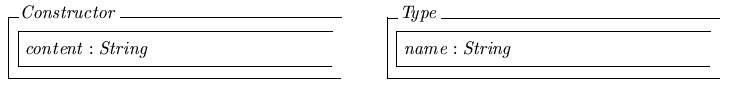
Type identifies a type definition. Besides the given type such as N and B, there are also user defined types. The name attribute indicates the name of the new type.
A mixed type is either a constructor or a defined type which is modeled by a class union [5], where ¯Type denotes a union of all classes defined by inheriting Type. A declaration type can be composed of a sequence of mixed types, i.e. P A, A ® B and so on. A predicate occupies the similar syntactic category as a type declaration in our level abstraction. A global definition can be either a type definition or an axiom definition.
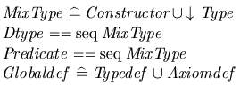
Type definition Typedef is for defining user given types such as simple type, abbreviation and free types. Axiom definition Axiomdef is used to define global constants or functions such as liberal, generic and unique functions.
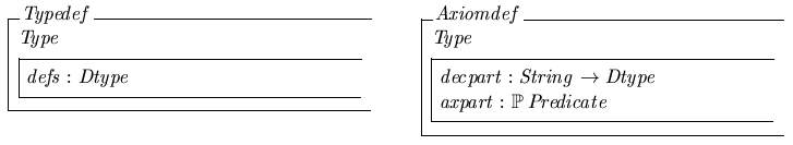
The declaration part decpart is a set of pairs, where the first element of a pair is a variable name and the second is the variable's type declaration. Note that the function is used here to indicate that one variable can only have one type declaration. The axiom part axpart consists a set of predicates, which states the properties of a particular schema.
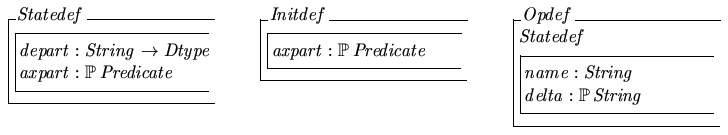
The Object-Z state, initial and operation schemas are modeled as:
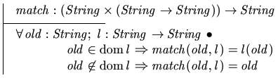
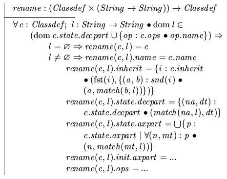
The match function is used to find the corresponding item in an item list. Note that if an item is not in the given list it returns itself.
The function rename captures the class renaming facilities. Given a class and a renaming list, and the function returns the renamed class.
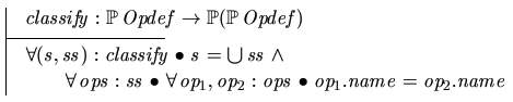
Function classify takes in a set of operation definition and divides them into subsets, which within each subset the name of the operation is the same.
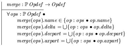
The function merge merges a set of same named operations into only single operation definition.
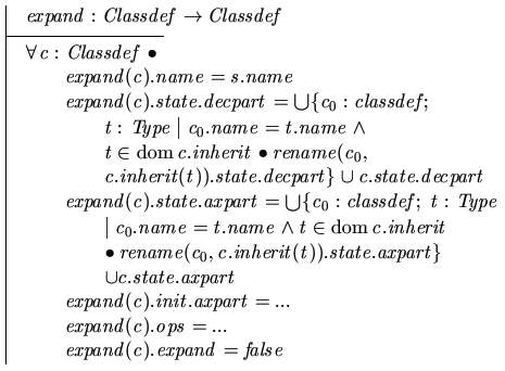
The expand function expands a class definition according to its inheritance list, and outputs the expanded class.
The Object-Z class is modeled as:
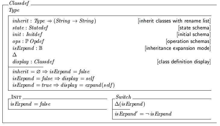
As for the inheritance expansion purpose we introduced two more attributes. The boolean attribute isExpand records the current status of expansion. Depending on the value of isExpand, a secondary variable [7] display references the corresponding class definitions (either expanded or non-expanded version). An operation Switch that changes the status of the expansion mode will implicitly change the displaying class.
An Object-Z specification is a collection of global definitions and class definitions.
- OZSpec == P (Globaldef È Classdef)
Finally, the web browsing environment is modeled as:
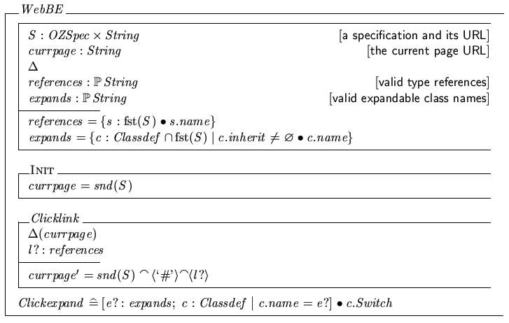
There are two major operations for clicking on either type links or on the derived class names. The Clicklink operation will jump from the current context position (a type declaration) to its corresponding type definition position within the scope of the specification. The operation Clickexpand will change the status of the expansion mode and eventually changing the displayed class definition.
3.2 Formal model of the projection facilities
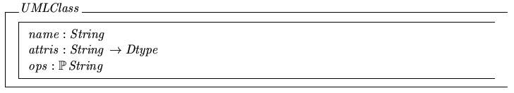
A UML class consists of a class name, a set of attributes and a set of operation names.
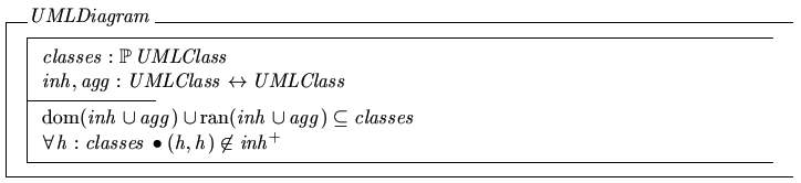
A UML diagram UMLDiagram is a collection of UML classes and together with their relationships to each other such as inheritance and aggregation.
A function project models the transformation from an Object-Z specification to a UML class diagram.
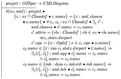
Note that our projection function from Object-Z specifications to UML diagrams focus on UML class diagrams at the current stage. The projection to UML behaviour diagrams such as statecharts may not be uniquely determined given an Object-Z specification. We will discuss about the projection to statechart diagrams further in Section 6.
4. Main Implementation Issues and Related Background
Pure Z notation on the web based on HTML and Java applet has also been investigated by Bowen and Chippington [1] and Cinancarini, Mascolo and Vitali [3]. HTML has been successful in presenting information on the Internet, however the lack of content information and overburdened of all kinds of tags have made the retrieval and exchange of resource become more and more difficult to perform.
Our work uses the latest technology of XML and XSL for displaying and transforming object-Z notation on the web. The users only need to follow the defined syntax in writing the XML document, the layout part is user transparent. Our XML format is inspired by the work (Java applet) of Cinancarini at el [3] however we use different technology XML/XSL. The developed XML/XSL web environment covers not only the pure Z notation but also Object-Z with inheritance expansion facilities. Furthermore, the projection tools from Object-Z to UML are built into our system. The conceptual projection techniques are derived from our research on linking UML with Object-Z [11], which are similar to the translation rules developed by Kim and Carrington [10]. The difference is that we are working on the projection from Object-Z to UML where Kim and Carrington focus on translating UML to a partial Object-Z specification (a different direction from ours). Other work on linking Z and UML mainly concentrates on using Z to define the semantics for UML class diagrams.
The reason that we chose XML rather than MathML is due to its extensibility. Though MathML is rich in writing mathematical expressions, the document structure is not suitable for authoring formal specification language such as Object-Z. For example, the Object-Z schemabox is more difficult to be constructed in MathML. Furthermore, MathML usually consists of heavy load of defined tags, which is unbearable for the authors whose focus is on the abstraction of the model rather than the structure of the expressions themselves. Furthermore, we want to construct a web environment as close as possible to the LaTeX style file for Object-Z (oz.sty) so that a simple translation tool can be developed to map existing Object-Z specifications in LaTeX to our web XML format.
The main process and techniques for developing Object-Z web environment and projections to UML are depicted by Figure 1. In the following sections, we use Object-Z graph example to facilitate the detailed discussion of our implementation approaches.
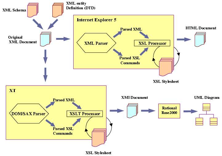
Figure 1: overall diagram
The formal model defined in Section 3 is acted as a precise design reference document and provides clear guidelines to our XML/XSL implementations. For example, the XSL codes for implementing inheritance expansion in Section 5 is based on the $expand$ function defined in Section 3.1; the XSLT codes for projecting Object-Z to UML in Section 6 is based on the project function defined in Section 3.2.
5. Object-Z Web Environment
Firstly, we define a customized XML document for Object-Z according to its syntax definitions of the previous section. This document is used for checking the syntax validity of the user input specifications in XML. The World Wide Web Consortium (W3C) has provided two mechanisms for describing XML structures: Document Type Definition (DTD) and XML Schema. The former is originated from SGML Recommendation and used a total different syntax. XML Schema is a kind of XML file itself and is going to play the role of DTD in defining customized XML structure in the future. It is consistent with XML syntax and easy to write over DTD. We use XML Schema to define our XML structure syntax for Object-Z. Part of the XML Schema (for defining an Object-Z operation schema) is as follows:
<?xml version="1.0" encoding="UTF-8"?>
<Schema xmlns="urn:schemas-microsoft-com:xml-data"
xmlns:dt="urn:schemas-microsoft-com:datatypes">
<!-- some definition omitted -->
<ElementType name="op" content="eltOnly" order="seq">
  <element type="name" minOccurs="1" maxOccurs="1"/>
  <element type="delta" minOccurs="0" maxOccurs="1"/>
  <element type="decl" minOccurs="0" maxOccurs="*"/>
  <element type="st" minOccurs="0" maxOccurs="1"/>
  <element type="predicate" minOccurs="0"
    maxOccurs="*"/>
  <AttributeType name="layout" dt:type="enumeration"
    dt:values="simpl calc" default="simpl"/>
  <attribute type="layout"/>
<ElementType> <ElementType name="classdef"
  content="eltOnly">
  <!-- some definition omitted -->
  <element type="op" minOccurs="0" maxOccurs="*"/>
  <!-- some definition omitted -->
</ElementType>
<!-- some definition omitted -->
</Schema>
It states that the op tag is an element of classdef and consists of one name, a delta list, a number of declarations decl, an horizontal line st and some predicate definitions. An attribute layout is defined to distinguish between vertical layout schemas simpl and horizontal layout schemas calc.
Object-Z languages consists of a rich set of mathematical symbols. Those symbols can be presented directly in Unicode which is supported by XML. We have defined all entities in the DTD so that users do not have to memorize all the Unicode numbers when authoring their XML documents. Part of the entity declaration DTD is defined as follows:
<?xml version="1.0" encoding="UTF-8"?> <!-- some definition omitted here --> <!ENTITY emptyset "࢝"> <!ENTITY mem "∈"> <!ENTITY pset "ℙ"> <!ENTITY uni "∪">
As most existing Object-Z specifications were constructed in LaTeX, translating them to our format can be a trivial task due to that each entity is given a Object-Z LaTeX compatible name. DTD is chosen to define our entity declaration because XML Schema does not support entity declaration at the moment. When authoring XML files, the user simply declares the name space of the XML schema and Entity DTD file as follows.
<?xml version="1.0" encoding="UTF-8"?>
<! --some definition omitted here -->
<!DOCTYPE unicode SYSTEM
  "http://nt-appn.comp.nus.edu.sg/fm/zml/unicode.dtd">
<objectZnotation xmlns="x-schema:
  http://nt-appn.comp.nus.edu.sg/fm/zml/objectZschema.xml"
  xmlns:HTML="http://www.w3.org/Profiles
    /XHTML-transitional">
<!-- some definition omitted here -->
</objectZnotation>
With the above name space links, the XML editing tools can check the validity of the file via XML Schema definition and the DTD entity declarations. Any unspecified structures and entity symbols would be reported as a syntax error. The following is the Web browsing environment for the DAG class (of the graphs specification example) in our XML format.
<classdef layout="simpl" align="left">
<name>DAG</name>
<inherit>
<type>Collection</type>
<rename>nodes/elemts</rename>
</inherit>
<state>
<decl>
<name>linkto</name>
<dtype>
<type>T</type>&rel;<type>T</type>
</dtype>
</decl>
<st/>
<predicate>&dom;linkto&uni;&ran;linkto⊂nodes</predicate>
<predicate>&nexi;n:nodes˙(n,n)&mem;linkto+</predicate>
</state>
<op layout="simpl">
<name>Delete</name>
<delta>(linkto)</delta>
<st/>
<predicate>linkto'={x!}&dsub;linkto&rsub;{x!}</predicate>
</op>
<op layout="simpl">
<name>AddLink</name>
...
</op>
<op layout="simpl">
<name>DeleteLink</name>
...
</op>
</classdef>
With a valid XML file in hand, the next step is to transform the XML file into HTML format and display it on the web. XSL is a stylesheet language to describe rules for matching and transforming XML documents. An XSL file is a XML document itself and it can perform the transformation between XML to HTML, XML to XML, XSL to XSL and so on. This kind of transformation can be done on the server side or the client side. Since Internet Explorer 5 (IE5) has already supported XSL technology, our environment is based on client side (browser) transformation. A partial XSL stylesheet segment for displaying operation op and class definition classdef are defined as below.
<xsl:template match="op[@layout='simpl']">
<html>
<table>
  <tr>
    <!-- some definition omitted here -->
    <td height="24" valign="middle" align="left" nowrap="true">
      <i><xsl:value-of select="name"/></i>
      <!-- some definition omitted here -->
    </td>
    <!-- some definition omitted here -->
  </tr>
  <xsl:for-each select="delta | decl">
    <xsl:apply-templates select="."/>
  </xsl:for-each>
  <xsl:apply-templates select="st"/>
  <xsl:for-each select="predicate">
    <xsl:apply-templates select="."/>
  </xsl:for-each>
  <tr>
    <!-- some definition omitted here -->
  </tr>
</html>
</xsl:template>

<xsl:template match="classdef[@layout='simpl'] | classdef[@layout='gen']">
<html>
</table>
  <a><xsl:attribute name="name"><xsl:value-of select="name"/></xsl:attribute></a>
  <!-- some definition omitted here -->
  <xsl:apply-templates select="tydef"/>
  <xsl:apply-templates select="state"/>
  <xsl:apply-templates select="init"/>
  <xsl:apply-templates select="op"/>
  <!-- some definition omitted here -->
</html>
</xsl:template>
XSL stylesheet defines match method for each customized tag in the XML structure and describes the corresponding HTML codes. From the example above, in matching the "op" tag the XSL will display the operation name, delta list, declaration and predicates accordingly; in matching the "classdef" tag the XSL will first convert the class name into a HTML bookmark for the type reference usage and then apply the templates of drawing local type definition, state schema, initiation schema, operations and so on. To apply a template in XML is like to make a function call in programming, and each template will perform its own transformation. When authoring Object-Z specifications in our XML format, the users only need to construct their XML files and add an URL to the defined XSL stylesheet location as follows.
<?xml version="1.0" encoding="UTF-8"?>
<?xml-stylesheet type="text/xsl"
 href="http://nt-appn.comp.nus.edu.sg/fm/zml/objectzed.xsl"?>
With this link, the browser (IE5) will automatically transform XML document into desired HTML output. This process is totally user transparent and much faster than those Java applet approaches [1, 3]. For example, the Collection and DAG classes in XML format specified previously is transformed into HTML as in Figure 2.
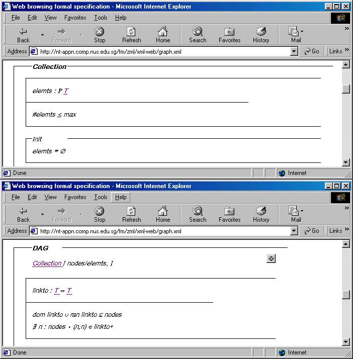
Figure 2: Collection and DAG
A full demonstration of the graph specification example is available at
The aim of class inheritance expansion is to allow user to view the full definition of a derived class. In the DAG class case (in the bottom side of the Figure 2), when a user click the '+' link, (the concrete representation of isExpand attribute of the class Classdef in Section 3.1), the full definition of class of "DAG" will be shown. This implementation is based on the inheritance expansion rules defined in the expand function of Section 3.1. Clicking '-' link (when isExpand is true) is for going back to the un-expanded version.
The core part of the expansion techniques uses the match facilities provided by XSL to find the corresponding definitions in the parent class and merge them in the derived class. Part of the XSL for merging the declarations in the state schema of a class is as follow.
<xsl:for-each select="//classdef[name=context(-1)/inherit/type]/state/decl">
<!-- some definition omitted here -->
</xsl:for-each>
<xsl:for-each select="state/decl">
<!-- some definition omitted here -->
</xsl:for-each>
<!-- some definition omitted here -->
The next section is focused on projecting Object-Z models (in XML) to UML diagrams (in XMI).
6. UML Photos
UML can be used to visualize the Object-Z models. As introduced earlier, the Object-Z models can be constructed in XML format. The textual specifications of UML models are in XMI format. Based on XSL Transformations (XSLT) [15] technology, we define an XSL file to capture all translation rules from Object-Z XML to UML XMI. XT [4] is chosen as the XSLT processor and Rational Rose 2000 is used as the UML tool. By now we have fully implemented the visualization of static parts with UML class diagrams and are looking into the dynamic parts with UML statecharts. In our approach, all elements from the static view, such as attributes, operations, classes and their relationships (inheritance and aggregation) can be successfully captured through the transformation process.
The XML file for formal specifications and the XMI file for UML diagrams have similar structures (an observation from their formal models defined in Section 3). An XMI file has the structure as follows:
<XMI xmi.version="1.0">
  <XMI.header>
  <XMI.content>
  <XMI.extensions>
</XMI>
The XMI.header section includes some optional information about UML model. Elements in UML diagrams, such as classes in class diagrams and states in the statecharts, are specified in the XMI.content section, while their layout, colors and other displaying properties are specified in the XMI.extensions section.
The XSL file used in this section is the implementation of the transformation rules (abstractly defined in formal models, the project function, in Section 3.2) and the file is consistent with UML.DTD. The template technology plays a key role in implementing the translation rules. Consider the implementation issues and the translation rules based on the formal model, the following guidelines are formed:
- Each class in Object-Z XML models corresponds to a class in UML XMI models. They have the same name, attributes and operations.
- If a type value in the Inherit part of a class matches the name of any other class in the current XML file, we regard that former class inherits the second one and illustrate the inheritance relationship between these two classes in the UML class diagram. In the case of spelling mistakes or missing reference of the Inherit type, we ignore the relationship.
- If a type value in the decl part, that is, the type of an attribute, matches the name of any class in current XML file, this is regarded as aggregation relationship between these two classes. The cardinality of the aggregation will be calculated and classified into UML aggregation ranges.
Due to the space limitation (XMI files for UML models are normally very large and complex with all details about property specifications), only the sketch of a simplified XMI unit---class Collection, is given as an example in the paper.
<Foundation.Core.Class xmi.id = ' S.10001 '>
        <name> Collection
        <namespace>
                <xmi.idref = 'G.1'/>
        </namespace>
        <GeneralizableElement.specialization>
                <xmi.idref = ' G.8 '/>
                <!-- { DAG -> Collection }-->
        </GeneralizableElement.specialization>
        <Classifier.feature>
                <Attribute xmi.id = ' S.10002 '>
                        <name> name
                        <multiplicity>1
                        </multiplicity>
                        <DataType xmi.idref = ' G.5 '/>
                                <!-- N -->
                </Attribute>
                <Attribute xmi.id = ' S.10003 '>
                        <name> elemts </name>
                        <multiplicity>1
                        </multiplicity>
                        <DataType xmi.idref = ' G.6 '/>
                                <!-- T -->
                </Attribute>
                <Operation xmi.id = ' S.10004 '>
                        <name>Init</name>
                </Operation>
                <Operation xmi.id = ' S.10005 '>
                        <name> Add </name>
                </Operation>
                <Operation xmi.id = ' S.10006 '>
                        <name> Delete </name>
                </Operation>
        </Classifier.feature>
</Foundation.Core.Class>
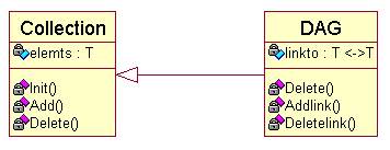
Figure 3: Generated Class Diagram
As in figure 3, the UML class diagram depicts the static view of the four graph classes constructed from the previous sections. All attributes and operations match their definitions in the formal model. Now we demonstrate how the relationships between classes are captured during the transformation.
The relationship between $Collection$ and DAG is Inheritence. This relationship in XMI segment is as following (simplified):
<Foundation.Core.Generalization xmi.id = ' G.8 '>
        <name/>
        <Generalization.subtype>
                <Class xmi.idref = ' S.10007 '/>
                        <!-- DAG -->
        </Generalization.subtype>
        <Generalization.supertype>
                <Class xmi.idref = ' S.10001 '/>
                        <!-- Collection -->
        </Generalization.supertype>
</Foundation.Core.Generalization>
Currently we are investigating the dynamic view transformation. The semantic links between Object-Z class and UML statecharts are:
- the Object-Z operation names are corresponding to UML statechart transition links between states,
- the Object-Z operation pre-conditions are corresponding to the guards of the UML state transition links,
- the boundary values of the state variables of an Object-Z class determine the states of the UML statechart diagram.
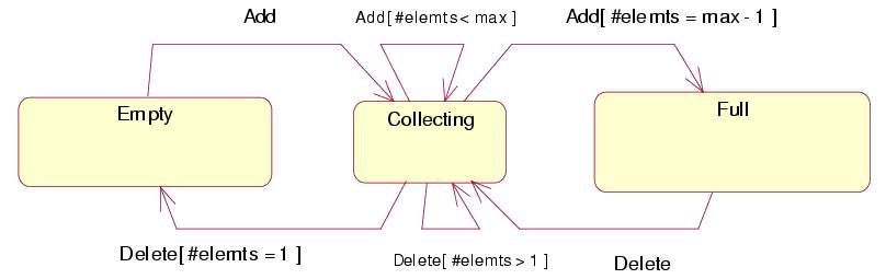
Figure 4: Collection statechart
Based on these semantic links, a statechart diagram for the class Collection may be constructed as Figure 4. Unlike the projection from Object-Z to UML class diagram, the projection to UML behaviour diagrams such as statecharts may not be uniquely determined. A certain level of user interaction may be necessary in the projection tool. We are in the process of developing an interaction tool based on the rules above.
Brief structures of a simplestate Empty and a transition (from Collecting to Empty) in the statechart in XMI are:
<State_Machines.SimpleState xmi.id="G.21">
  <name>Empty</name>
</State_Machines.SimpleState>

<State_Machines.Transition xmi.id="G.24">
  <name />
  <source>
        <SimpleState xmi.idref="G.22" />
        <!-- Collecting  -->
  </source>
  <target>
        <SimpleState xmi.idref="G.23" />
        <!-- Empty  -->
  </target>
  <trigger>
        <SignalEvent xmi.idref="G.28" />
        <!-- Delete   -->
  </trigger>
  <guard>
        <Guard xmi.id = 'G.30' />
        <expression>
               #elements = 1
        </expression>
  </guard>
</State_Machines.Transition>
The documentation about Object-Z to UML transformation and downloadable codes are available at:
7. Conclusion
The first contribution of this paper is the demonstration of the XML/XSL approach to the development of a web environment for Object-Z. The web environment includes the auto referencing and browsing facilities for the Object-Z inheritance expansions. Very recently, we has extended this web environment to accommodate the newly developed formal modeling notation Timed Communicating Object Z (TCOZ) [12] (an integration of Object-Z and Timed-CSP [13]). Additional inheritance rules for active class defined in TCOZ [6] have been added in our web environment. Our ideas for putting Z family (Z/Object-Z/TCOZ) on the Web can be easily adopted by other formal specification notations, such as VDM and VDM++. In fact, since TCOZ includes most Timed CSP constructs, its web environment can be used for process algebra (CSP/Timed-CSP) specifications. Perhaps this may create a new culture for constructing formal specifications on the web in XML rather than in LaTeX. We hope it can be the starting point for developing a standard XML environment for all formal notations --- Formal specification Markup Language (FML). This may also make an impact on formal methods education through the web.
The second contribution of this work is the investigation of the semantic links and web transformation environment (XSLT) between Object-Z (in XML) with UML diagrams (in XMI). Although we have some ideas on Object-Z behaviour projections to statecharts, the development of the Web environment for systematic transformation from Object-Z/TCOZ to statechart/collaboration diagrams remains a challenge.
The third contribution of this paper is the demonstration of a formal approach to modeling web applications. Object-Z (itself) has been used to specify and design the essential functionalities of the Object-Z web environment and projection tools to UML. We've found that the formal model can be used as a precise design document and also provide clear guidelines to our XML/XSL implementations.
Acknowledgments
This work is supported by the academic research grants, Integrated Formal Methods (R-252-000-050-107) and Adding Formality to UML (R-252-000-076-112) from National University of Singapore.
References
- [1]
- J. P. Bowen and D. Chippington. Z on the Web using Java. In Bowen et al. [2], pages 66--80.
- [2]
- J. P. Bowen, A. Fett, and M. G. Hinchey, editors. ZUM'98 : The Z Formal Specification Notation, 11th International Conference of Z Users, Berlin, Germany, volume 1493 of LNCS Springer-Verlag, Sep 1998.
- [3]
- P. Ciancarini, C. Mascolo, and F. Vitali. Visualizing Z notation in HTML documents. In Bowen et al. [2], pages 81--95.
- [4]
- James Clark. Xt version 19991105. http://www.jclark.com/xml/xt.html, 1999.
- [5]
- J. S. Dong and R. Duke. Class Union and Polymorphism. TOOLS 12, pages 181--190. Prentice-Hall, November 1993.
- [6]
- J. S. Dong and B. Mahony. Active Objects in TCOZ. The 2nd IEEE International Conference on Formal Engineering Methods (ICFEM'98), pages 16--25. IEEE Press, Dec 1998.
- [7]
- J. S. Dong, G. Rose, and R. Duke. The Role of Secondary Attributes in Formal Object Modelling. The First IEEE International Conference on Engineering Complex Computer Systems (ICECCS'95), pages 31--38, Ft. Lauderdale, USA, Nov 1995. IEEE Press.
- [8]
- R. Duke and G. Rose. Formal Object Oriented Specification Using Object-Z. Cornerstones of Computing. Macmillan, March 2000.
- [9]
- A. S. Evans and A. N. Clark. Foundations of the unified modeling language. BCS-FACS Northern Formal Methods Workshop, Springer Verlag, 1998.
- [10]
- S. K. Kim and D. Carrington. An Integrated Framework with UML and Object-Z for Developing a Precise Specification. The 7th Asia-Pacific Software Engineering Conference (APSEC'99), pages 240--248. IEEE Press, 2000.
- [11]
- J. Liu, J. S. Dong, B. Mahony, and K. Shi. Linking uml with integrated formal techniques. Unified Modeling Language: Systems Analysis, Design, and Development Issues. 2000.
- [12]
- B. Mahony and J. S. Dong. Timed Communicating Object Z. IEEE Transactions on Software Engineering, 26(2):150--177, February 2000.
- [13]
- S. Schneider and J. Davies. A brief history of Timed CSP. Theoretical Computer Science, 138, 1995.
- [14]
- G. Smith. The Object-Z Specification Language. Advances in Formal Methods. Kluwer Academic Publishers, 2000.
- [15]
- World Wide Web Consortium (W3C). Xsl transformations (xslt) version 1.0. http://www.w3.org/TR/xslt, 1999.
- [16]
- World Wide Web Consortium (W3C). Extensible markup language (xml). http://www.w3.org/XML, 2000.
- [17]
- World Wide Web Consortium (W3C). Extensible stylesheet language (xsl). http://www.w3.org/Style/XSL, 2000.
- [18]
- J. Woodcock and J. Davies. Using Z: Specification, Refinement, and Proof. Prentice-Hall International, 1996.