Experience with Perspective Shadow Maps
(draft
for a chapter of the diploma thesis by Tobias Martin,
1. Introduction
Perspective shadow maps technique was presented in SIGGRAPH
2002:
Stamminger
M. and Drettakis G. 2002. Perspective Shadow Maps. In Proceedings of SIGGRAPH 2002, 21(3), 557—562. See:
http://www-sop.inria.fr/reves/personnel/Marc.Stamminger/psm/
It is a form of shadow map approach to generate shadows.
Shadow maps were proposed by L. Williams in 1978. Instead of the original idea
of Williams of generating shadow map from the world space, perspective shadow
maps technique generates shadow maps in normalized device coordinate space,
i.e., after perspective transformation. The paper claims that it results in
important reduction of shadow map aliasing with almost no overhead, and can
directly replace standard shadow maps for interactive hardware accelerated
rendering as well as in high-quality, offline renderers. This is an interesting
idea and has generated lots of discussions in various forums of the graphics
community. However, there is no known published implementation of the technique
available for experimentation, and the hints on implementation in the paper’s
website were not very comprehensive. In this chapter, we describe our
experience in implementing PSM to better understand its mechanisms and results
and to compare it to our proposed trapezoidal shadow maps (TSM).
2.
As mentioned, perspective shadow maps technique works
similar to that of standard shadow maps (SSM), with the exception that the
shadow map is now captured in the post-perspective space (PPS) of the eye
rather than in the world space. So, the two-pass algorithm of Williams (1978)
for the SSM is adapted as follows. In the first pass, the scene (together with
the light) is first transformed to the PPS and then being rendered from the
viewpoint of the (transformed) light with depth buffer enabled. This buffer is
read or stored into an image called perspective
shadow map (PSM). In the second pass, the scene is rendered from the camera
viewpoint incorporating shadow determination for each fragment. A fragment is
in shadow if its z-value when transformed into the light’s view in
post-perspective space is greater than its corresponding
depth value stored in the shadow map.
In implementing PSM, we realize there are a number of
possible variations with different implementation challenges and rendering
outcomes. In the following, we describe the (first pass) capturing of the
perspective shadow map with OpenGL in three steps, and also zoom into a few
implementation choices in some steps of the technique. Note that the second pass
is essentially the same as that of the SSM with the use of a different
transformation matrix.
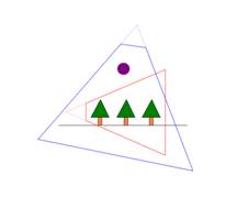
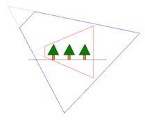
Step 1: Space for transformation to PPS.
To prepare the PPS for the light to capture a PSM in Step 3,
there are two considerations that result in possibly many different
implementations. First, when the eye’s frustum does not include all objects
that can cast shadow (as shown in Figure 1(i)), then in the PPS that transforms
the eye’s frustum to a unit cube, these objects remain outside the unit cube.
For the transformed light to capture a PSM here, these objects must still be inside
the frustum of the transformed light. More specifically, the near plane of the
transformed light must be carefully chosen and not simply be pushed till it
touches the unit cube. Second, consider the case when the light is behind the
eye as shown in Figure 1(ii). This is the case when the light, with respect to
the eye’s plane, lies on the different side as the far plane, then in the PPS
that transforms the eye’s frustum to a unit cube, the light’s position is
inverted relative to those objects in the eye’s frustum. For such a PSM
captured in Step 3, the second pass fragment depth comparison has to be
inverted too. Also, objects as in Figure 1(i) that outside the eye’s frustum
but inside the light’s frustum may also appear in Figure 1(ii) so that special treatment
to these objects is also needed.
|
|
|
|
Figure 1(i). The
eye’s frustum is in red, the light in front of the eye with its frustum in
blue, and a purple object outside the eye’s frustum but inside the light’s
frustum that will cast shadows into the eye’s frustum. |
Figure 1(ii). The
light is behind the eye, and the PPS transformed the eye’s frustum to a unit
cube will invert the light’s position relative to the objects in the eye’s
frustum. |
One unified way to resolve both of the above while still
keeps the algorithm non-complex is presented in Section 3 and 4 of the paper
with the use of 3D convex hulls and their intersections (see Figure 6 of the
paper), and the corporation of moving virtually the eye’s position backward to enlarge
the eye’s frustum. The new eye’s frustum resulted by the new position of the
eye, called it virtual eye, then
includes all objects casting shadows while also puts the light in front of the
(virtual) eye.
We realize many possibilities in moving the eye’s position
backward and other implications that do not seem to be discussed explicitly by
the paper. Below are some of these considerations in our implementation:
-
First,
in a simple case as shown in Figure 7 (upper right) of the paper, the virtual
eye’s position can be obtained by joining lines passing through the vertices of
the far plane with the extremal vertices of objects that can cast shadow. These
lines intersect the directed line, passing through the eye’s position and
parallel to the eye’s viewing direction, at a position behind the actual eye’s
position. The furthest such position can be used as the position of the virtual
eye.
-
Second,
objects that can cast shadow may, however, be huge such as those larger than
the far plane in size (refer to the paper, this also happens when the region of
interest H as defined is bigger than
the far plane) that the above mentioned lines do not intersect behind but in
front of the actual eye’s position. In this case, besides moving the eye’s
position, we need to enlarge or maintain the current fovy (while in the
previous case, a smaller fovy is used for the virtual eye’s frustum as there is
no change to the far plane). As such, it is not clear how to obtain an
“optimal” position for the virtual eye. One possible implementation is to do a
binary search of some fixed maximum number of steps to locate a good position
for the virtual eye behind the current eye’s position.
-
Third,
once a virtual eye’s position is located, there is a choice of whether to push
the near plane closer to the far plane without removing any objects casting
shadow outside the frustum. This is to minimize the space be transformed to PPS
so as to obtain higher resolution on the shadow map.
The above computation results in a frustum, either is the
original eye’s frustum or the enlarged virtual eye’s frustum. The matrix P’ to transform this frustum to PPS is
simply a projection matrix P
multiplying with the model view matrix M
where P is obtained with glFrustum or gluPerspective command in OpenGL to specify the frustum and M is the matrix to bring objects to the
world space with gluLookAt
command in OpenGL.
Step 2: Light Transformation to PPS.
The matrix P’ that
performs the transformation to the PPS is then used to transform the light’s
position and direction vectors to the PPS too. We note that the outcomes of the
transformation are in homogeneous coordinates and thus homogenous divisions on
those two vectors are necessary when using these vectors for subsequent
computations as in the next step.
Step 3: PPS to PSM.
The above two steps have prepared the scene to be captured
as a perspective shadow map from the transformed light’s position in the
transformed light’s direction. As usual with OpenGL, we need to set up the
required projection matrix P” and
model view matrix M” to render the
scene into a shadow map. M” is
straightforward – just used directly the two transformed vectors in Step 2. On
the other hand, P” can be implemented
with a few possible variations with glFrustum
or gluPerspective command in OpenGL.
To get good shadow maps, the (virtual) light’s frustum should tightly enclose
the eye’s frustum in PPS, which is a unit cube. So, there are two areas that
need attention:
-
The
near plane of the light should be as close as possible to the unit cube. In
other words, we would like to push the near plane closer to the far plane while
still capturing the whole unit cube and all objects outside the unit cube that
can still cast shadows into the unit cube as discussed in Figure 1.
-
The
fovy of the light should be as small as possible while still capturing the
whole unit cube and all objects outside the unit cube that can still cast
shadows into the unit cube. In general this requires a non-symmetrical viewing
frustum which is however more computationally challenging. One quick
implementation is to set fovy as twice the maximum angle among the eight angles
between the vectors of the center of projection of the light and the eight
vertices of the unit cube. This is however not the best as the computed light’s
frustum does not tightly fit to the unit cube (except for one vertex of the
unit cube).
3. Implementation
We implemented the PSM technique in Mandrake
Linux PC environment on an Intel Pentium IV 1.8GHz CPU with a NVidia GeForce
FX5900 ultra graphics controller using OpenGL. The T&L unit is replaced with
GL_vertex_program_ARB and the shading (inclusive of shadow comparison) is done
with GL_fragment_program_ARB. Linux environment is used here as we needed gmp (an arbitrarily long arithmetic
library) to get a more robust 3D convex hull implementation. gmp is not available in MS windows
environment. We note that our first implementation of the proposed TSM was in
the Microsoft Windows PC environment on an Intel Pentium IV 1.6 GHz CPU with a
GeForce Ti4400 graphics controller using OpenGL, but we have ported it, together with our standard
shadow map (SSM) and bounding box approximation (BB), to Linux for purposes of
comparison with PSM.
As indicated in the last section, there are many
implementation choices for PSM. For purposes of comparison with TSM, we devote
lots of effort to replicate the description provided in the PSM paper and to
tune to the best of our knowledge the algorithm in flavor of our test scenes. It
remains possible that our implementation may not be as efficient or effective
as the original implementation of PSM. The following are some challenges
encountered during the implementation:
-
The
3D convex hull adaptation was not a small effort due to the numerical stability
(i.e. robustness) issue. The possibility of dynamically updating the convex
hull is explored in order to save computational effort in the repeated
calculation of 3D convex hull for each frame. This is not implemented as such
dynamic update is again non-trivial to achieve.
-
In
our implementation, we adapted the binary search approach to locate the virtual
eye when it is necessary. For practical purposes, we limit our search to 8
iterations as each involves some significant effort of 3D convex hull
computations.
-
It
is suggested by the paper that one could possibly read back the depth buffer in
an effort to know how much to push a near plane closer to a far plane. This
however is expensive and thus a great penalty on the frame rate. It is
unacceptable for highly interactive applications with our current hardware
configuration. On the other hand, we do push the near plane of the virtual eye
towards its far plane as much as possible geometrically (till it touches H as defined in the paper) in order to
obtain high shadow map resolutions.
4. Discussion
There are currently two test scenes in our experiments. The
first scene is a big plane with a small tree in the middle of the plane to
facilitate the development of PSM; the second scene is the fantasy scene (just
like those scenes in one of our target game applications) originally used in
testing our TSM. Below are major issues under consideration for being a good
and practical shadow mapping technique that we illustrate with our first scene
where appropriates. We have also generated video of all the approaches for the
second scene and they are available in our project webpage.
(A) Polygon Offset Problem.
Due to the image space property, shadow comparisons (second
pass of the algorithm) are performed with finite precision which causes the
problem of self-shadowing. This is addressed in general by finding a bias which
is added to the depth values of the shadow map to move the z-values slightly
away from the light. For PSM, this
problem is worsened because objects are scaled
non-uniformly in the PPS. Our experience testifies to this, and we note an
undesirable phenomenon. That is, when the eye does not move backward in the
computation of the PPS, a larger polygon offset is needed as compared to that
when the eye does move backward. This can be understood as in the latter case,
the PPS is approaching the standard world space and thus a smaller polygon
offset is sufficient. Such phenomenon makes it hard to define a good bias throughout
the program.
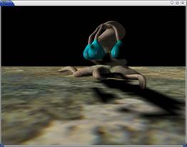
(B) Aliasing Problem.
As expected, we have high quality shadows from PSM than from
SSM as shown in, for example, Figure 2. The quality of the shadow is comparable
to that of TSM in such case too.
|
Figure 2(i). Standard
shadow map result for our first test scene. |
Figure 2(ii).
Perspective shadow map result for our first test scene in its good case
scenario. |
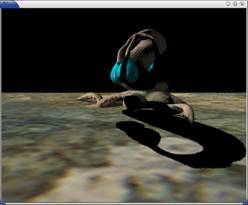
This is a good case for PSM where the light is not behind
the eye. The following Figure 3 shows the corresponding world and the PPS of
the various frustums.
|
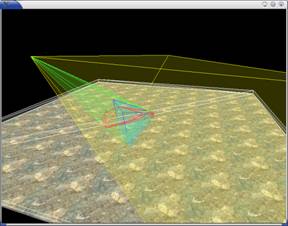
Figure 3(i). In the
world space, the light’s frustum is shown in yellow, and the eye’s frustum
blue. |
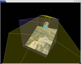
Figure 3(ii). In the
PPS, the light’s frustum is shown in yellow, and the virtual eye’s frustum as
a cube in blue. |
On the other hand, there are also bad scenarios for PSM. As
mentioned in the paper, PSM converges to SSM in some bad scenarios such as when
we need to move the eye’s position backward for a large distance. Our
experiments show that this is almost true but not quite accurate as we next
discussed with the following Figure 4.
|
Figure 4(i). In the
world space, the virtual eye’s frustum is shown in turquoise. |
Figure 4(ii). In the
PPS, the near plane of the light is shown in yellow, and the unit cube is
shown behind the near plane with the small tree remains small in the light’s
frustum. |
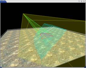
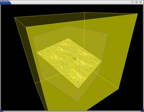
Figure 4(i) shows that there is a huge difference in the
sizes between the virtual and the original eye’s frustum. As such, the light’s
frustum is also enlarged, as a result those parts of the scene in the original
eye’s frustum is no longer enlarged for the capturing of shadow map. In such
case, shadows generated are of low quality as in the SSM. In actual fact, the
shadow generated with PPS may be worsened as shown in Figure 4(ii) as the unit
cube is “rotated” with respect to the light’s frustum. As such, the shadow map
generated with this light’s frustum is worse than that of SSM due to the irregular
orientation of the unit cube and thus wastage in the shadow map memory.
|
Figure 5(i). In the
world space, the light’s frustum is shown in yellow, the eye’s frustum blue,
and the virtual eye’s frustum turquoise. |
Figure 5(ii). In the
PPS, the scene in the unit cube appears only as a slice in the light’s
frustum (in yellow). |
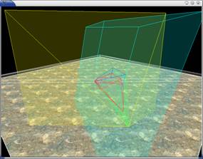
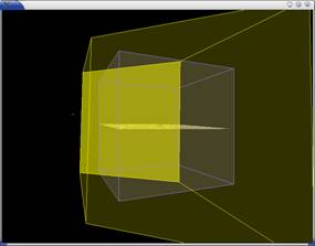
Figure 5 shows yet another bad scenario for PSM. Due to the
virtual eye’s frustum and the transformation to the PPS, the scene appears as a
thin slice in the light’s frustum. In this case, the shadow map memory is not
utilized wisely where most part is empty of the scene (as in our implementation
where unit cube is enclosed within the light’s frustum), and the shadow quality
is bad and at time disappears completely.
One way to avoid shadow disappearing
is to implement pushing the near plane of the eye closer to the scene. Figure
6(i) shows an enlarged version of another example of the previous figure, while
Figure 6(ii) shows the effect of pushing the near plane closer to the scene. In
doing so, the shadow map taken from the light’s view will get better
resolution. However, the implementation of this with reading back the depth
buffer to get a more accurate near distance can impact frame rate. Also, it is
not always possible to push near plane in a scene where dynamic objects close
to the near plane can appear and disappear.
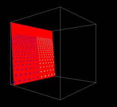
|
Figure 6(i). In the PPS, the eye is on the right side looking almost
orthogonal to the scene with white and blue spheres, and the light is on the
top of the unit cube. In this case, the shadow map is only a slice of the
scene. |
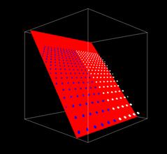
Figure 6(ii). Pushing the near plane of the eye closer to the far
plane, we can increase the resolution of the shadow map. |
As far as we know about our TSM approach, there are no such
bad cases as TSM does not have a transformation that brings the scene to
another space that is hard to visualize and with
“unexpected” scenarios to handle.
(C) Continuity Problem.
The continuity problem is very obvious with PSM where the
shadow quality changes drastically. As discussed in the implementation of PSM,
there are a few ways to improve shadow qualities such as the binary search to
locate a good virtual eye’s position, pushing a near plane (of the virtual eye
or the transformed light) closer to the corresponding far plane, the choice of
fovy for the virtual eye or the transformed light. All these, together with the
fact that dynamic new objects can affect the space to be transformed to PPS,
result in the use of drastically different shadow map resolution at subsequent frame,
and they are non-trivial to deal with so as to maintain a coherence shadow map
resolution.
Unlike what was mentioned in the paper, our experience shows
that the need to move eye to a virtual eye’s position is rather common while
navigating in our test scenes, in particular the complex one. As such, PSM has
a serious continuity problem that does not seem solvable at the moment. In fact, the shadows generated with SSM or BB
may be more acceptable than that of PSM as the former is more consistent and
with less drastic continuity problem for static objects.
5. Concluding Remark
On the whole, we reckon PSM is a very neat idea to address
aliasing problem in shadow maps. On the other hand, the implementation of PSM
is rather non-trivial with lots of possible tradeoffs that are hard to optimize,
and it needs lots of additional computation and data structure supports in CPU that
mapping it well to hardware does not seem possible presently. Besides solving some
cases of the aliasing problem, PSM does not seem to be a practical shadow map
technique in, for example, a game application where the scene is dynamic and
the eye can be moving anywhere, in front or behind the light!