UIT2201: Tutorial Set 10 (Fall 2016)
(Solution Sketch to Selected Problems)
** NOT TO BE GIVEN TO FUTURE UIT2201 STUDENTS **
T10-D1: (Logic Design) [From Quiz 2, Spring 2008] -- SOLN SKETCH
F = X(~Y) + (~X)Z + XYZ [4-AND, 2-OR gates]
(a)-------------------------------
X Y Z | F
-------------------------------
0 0 0 0
0 0 1 1
0 1 0 0
0 1 1 1
1 0 0 1
1 0 1 1
1 1 0 0
1 1 1 1
-------------------------------
(b) F = (~X)(~Y)Z + (~X)YZ + X(~Y)(~Z) + X(~Y)Z + XYZ [8-AND, 3-OR gates]
(c) Reasoning steps used while simplifying
1. Look out for "partner-pairs" like AB + A(~B)
we can simplify and "eliminate" B (make B disappear!)
Reason: AB + A(~B) = A(B + ~B) = A*1 = A
2. Because A = A + A, we can clone any product-term
F = (~X)(~Y)Z + (~X)YZ + X(~Y)(~Z) + X(~Y)Z + XYZ
(* Now, look for partner-pairs. Below, we clone X(~Y)Z *)
= [(~X)(~Y)Z + (~X)YZ] + [X(~Y)(~Z) + X(~Y)Z] + [X(^Y)Z + XYZ]
= (~X)Z(~Y + Y) + X(~Y)(~Z + Z) + AB(~C + C)
= (~X)Z + X(~Y) + XZ = Z(~X + X) + X(~Y)
= Z + X(~Y) [1-AND, 1-OR gate]
(d) DIY
OPTIONAL alternative method covered only in tutorials.
Using a ternary code to representing products.
In this method, we use a ternary code to represent product-terms:
000 == ~X~Y~Z 100 == X~Y~Z
001 == ~X~Y Z 101 == X~Y Z
010 == ~X Y~Z 110 == X~Y Z
011 == ~X Y Z 111 == X Y Z
We use a special code "*" to represent a "match-all" state. (In tut, I had used "X".)
Then we can do simplification as follows:
XY~Z + XYZ = XY(~Z+Z) = XY
110 + 111 = 11(0+1) == 11* (so 11* = 110 + 111)
Then parts (b) and (c) above can be done as follows:
(b) F = 001 + 011 + 100 + 101 + 111
(c) F = (001+011) + (100+101) + (101+111)
= 0*1 + 10* + 1*1 = (0*1+1*1) + 10* = **1 + 10* ==> Z + X(~Y)
This alternative method works better for some people, but may not be so easy to understand
for others. It is not covered in textbook [SG3].
Hence, it is optional, for your knowledge.
|
T10-D2: [Design of the 3-bit-Majority Circuit -- SOLUTION SKETCH]
---------------------
A B C | M
---------------------
0 0 0 0
0 0 1 0
0 1 0 0
0 1 1 1
1 0 0 0
1 0 1 1
1 1 0 1
1 1 1 1
-------------------- |
|
Here M means Majority
M = (~a)bc + a(~b)c + ab(~c) + abc
= [(~a)bc + abc] + [a(~b)c + abc] + [ab(~c) + abc]
M = bc + ac + ab
= bc + a(b+c)
This formula "says" that M is true iff at least
any two of inputs (a, b, or c) are 1's.
Can you "hear" it?) |
T10-D4: (Multiplexor Circuits) [2- and 4-input MUXes] -- SOLUTION SKETCH
(a) [2-input MUX] Use this MUX as "basic" circuit. It uses 2 AND gates and 1 OR gate.

To understand how this MUX works, you must dynamically work out the output F, for different input settings of the selector signal S.
For example, if S=0, then the output of the top AND-gate is D0 (because D0*1=D0), while the output of the bottom AND-gate is 0 (because D1*0=0). So, the output of the OR-gate is D0 (cause D0+0=D0).
(Now, you try it out for S=1.)
(b) [4-input MUX]
(i) Top-Down Decomposition:
 |
|
(ii) Bottom-Up Construction:
 |
(i) The first design uses top-down decomposition or
thinking mode and "reuses the result" (the 2-to-1 MUX design).
Its total size is 3 x (size of basic MUX) = 6 AND gates and 3 OR gates.
(ii) This second design uses bottom-up construction thinking mode and "reuse the method".
Note that, in its design, it uses 3-input AND gates, each
is equivalent to two 2-input AND gates.
Thus, total size of this design is 8 AND gates and 3 OR gates.
(This design uses 2 more AND gates.)
T10-Q1(a): (5 points) (Modified from Prob.18 (p.185, Ch.4) of [SG3] -- SOLN SKETCH
From TT : Output = (~a)(~b) + a(~b) + ab [3 AND-gates, 2 OR-gates]
Simplify: Output = [(~a)(~b) + a(~b)] + [a(~b) + ab]
= (~b) + a [1 OR-gate]
Logic Circuit -- DIY
OPTIONAL-alternative method:
Output = 00 + 10 + 11 = X0 + 1X = ~b + a
T10-Q1(b): (i) 6 2-input-AND gates. (ii) max-delay = 6d. (iii) min-delay = 3d.
T10-Q2: (Logic Design) -- SOLN SKETCH
F = XY + (~X)Z + XYZ [4-AND, 2-OR gates]
(a)-------------------------------
X Y Z | F
-------------------------------
0 0 0 0
0 0 1 1
0 1 0 0
0 1 1 1
1 0 0 0
1 0 1 1
1 1 0 1
1 1 1 1
-------------------------------
(b) F = (~X)(~Y)Z + (~X)YZ + X(~Y)Z + XY(~Z) + XYZ [8-AND, 3-OR gates]
(c) F = (~X)(~Y)Z + (~X)YZ + X(~Y)Z + XY(~Z) + XYZ
= [(~X)(~Y)Z + (~X)YZ] + [X(~Y)Z + XYZ] + [XY(~Z) + XYZ] (*XYZ cloned*)
= (~X)Z(~Y + Y) + XZ(~Y + Y) + XY(~Z + Z)
= (~X)Z + XZ + XY
= Z + XY [1-AND, 1-OR gate]
OPTIONAL-alternative:
F = 001 + 011 + 101 + 110 + 111 = (001+011) + (101+111) + (110+111)
= (0X1 + 1X1) + 11X
= XX1 + 11X = Z + XY
(d) DIY
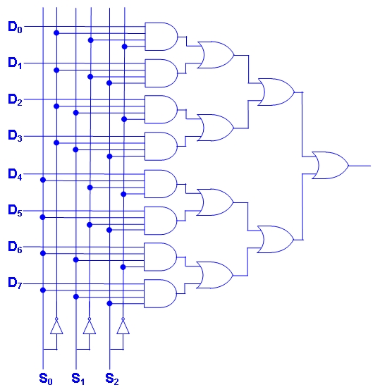
T10-Q3: (10 points) [8-input multiplexor] -- SOLUTION SKETCH
|
(Note: These are extensions of the 4-to-1 MUX designs in T11-D1.
The first uses 4-input AND gates, which can be decomposed into
three 2-input AND gates. The "reuse the method" design uses 24 AND gates
and 7 OR gates. The "reuse the result" design uses only 14 AND gates
and 7 OR gates.
Also, we can think of the truth table for the
8-to-1 MUX as shown here.)
|
|
-------------------------
S[2] S[1] S[0] | Output
-------------------------
0 0 0 | D0
0 0 1 | D1
0 1 0 | D2
0 1 1 | D3
1 0 0 | D4
1 0 1 | D5
1 1 0 | D6
1 1 1 | D7
------------------------
|
T11-Q4: (10 points) [3-to-8 Decoder Circuit]
 |
|
This uses 3-input AND gates; each will
decompose into two 2-input AND gates.
So, total of 16 2-input AND gates needed. |
UIT2201: CS & IT Revolution; (Fall 2104); A/P Leong HW