(-1, -1, 1, 1)^T = N_T * t_0

(+1, -1, 1, 1)^T = N_T * t_1

(+1, +1, 1, 1)^T = N_T * t_2

(-1, +1, 1, 1)^T = N_T * t_3
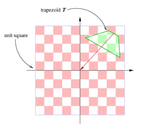
N_T and the maintainance of the polygon offset with fragment programs. In this document we assume you have read the TSM paper and you are able to calculate the four vertices of the trapezoid.
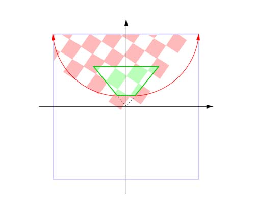
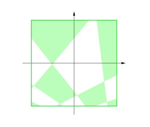
N_T (4x4 matrix) which maps the four corners of the trapezoid t_0, t_1, t_2, and t_3 to the front side of the unit cube, i.e. we want to calculate N_T with the following constraints:
|
|
|
T_1, R, T_2, H, S_1, N, T_3, and S_2):
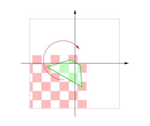
| 1. |
As a first step, T_1 transforms the center of the top edge to the origin (the vectors u = (x_u, y_u, z_u, w_u) and v = (x_v, y_v, z_v, w_v) hold intermediate results):
      |1 0 0 -x_u|
T_1 = |0 1 0 -y_u|
      |0 0 1   0 |
      |0 0 0   1 |
|
|
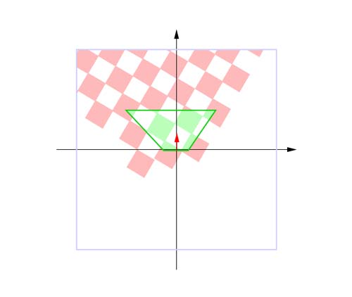
| 2. |
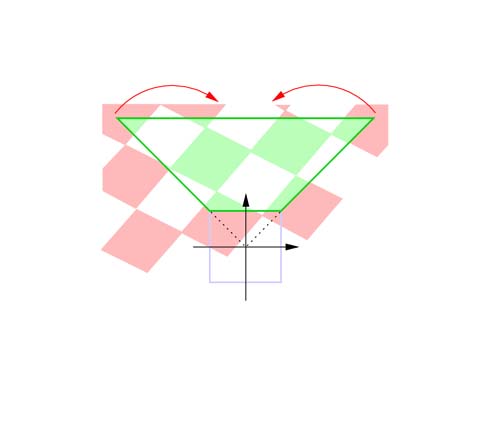
Then, the trapezoid T is rotated by applying R around the origin in such a way, that the top edge is colliniear with the x-axis:
    |x_u  y_u 0 0|
R = |y_u -x_u 0 0|
    | 0    0  1 0|
    | 0    0  0 1|
|
|
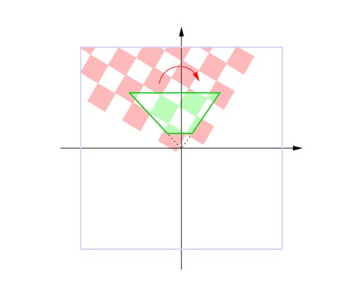
| 3. |
After step 2, the intersection i of the two side lines containing the two side edges (t_0, t_3) and (t_1, t_2) is transformed, by applying T_2, to the origin:
      |1 0 0 -x_u|
T_2 = |0 1 0 -y_u|
      |0 0 1   0 |
      |0 0 0   1 |
|
|
| 4. |
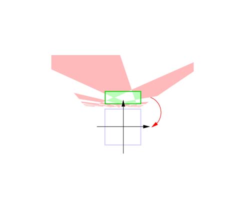
As a next step, the trapezoid has to be sheared with H, so that it is symmetrical to the y-axis, i.e. that the line passing through the center of the bottom edge and center of the top edge is collinear with the y-axis:
    |1 -x_u/y_u 0 0|
H = |0     1    0 0|
    |0     0    1 0|
    |0     0    0 1|
|
|
| 5. |
Now, the trapezoid is scaled by applying S_1, so that the angle between the two side lines containing the two side edges (t_0, t_3) and (t_1, t_2) is 90 degrees, and so that the distance between the top edge and the x-axis is 1:
      |1/x_u   0   0 0|
S_1 = |  0   1/y_u 0 0|
      |  0     0   1 0|
      |  0     0   0 1|
|
|
| 6. |
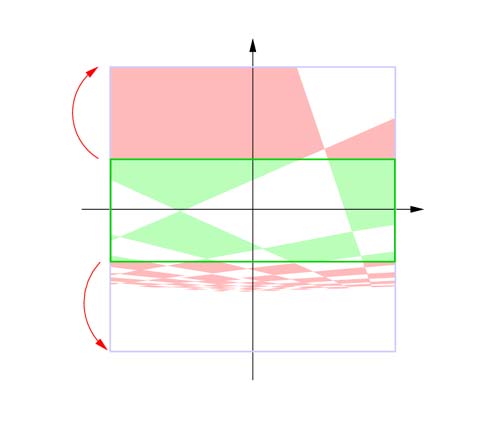
The following transformation N transforms the trapezoid to a rectangle:
    |1 0 0 0|
N = |0 1 0 1|
    |0 0 1 0|
    |0 1 0 0|
|
|
| 7. |
Then, the rectangle is translated along the y-axis until its center is coincident with the origin. This is done by applying T_3. After this transformation the rectangle is symmetrical to the x-axis as well:
      |1 0 0          0          |
T_3 = |0 1 0 -(y_u/w_u+y_v/w_v)/2|
      |0 0 1          0          |
      |0 0 0          1          |
|
|
| 8. |
As a last step the rectangle has to be scaled with S_2 along the y-axis so that it covers the front side ot the unit cube:
      |1     0     0 0|
S_2 = |0 -w_u/y_u  0 0|
      |0     0     1 0|
      |0     0     0 1|
|
|
Now the trapezoidal transformation N_T can be computed as follows:
|
|
#define ASSIGN_MAT(M, u0, u3, u6, u1, u4, u7, u2, u5, u8) { \
	M[0][0] = u0; M[0][1] = u3; M[0][2] = u6; \
	M[1][0] = u1; M[1][1] = u4; M[1][2] = u7; \
	M[2][0] = u2; M[2][1] = u5; M[2][2] = u8; \
	}

#define DET2(a, b, c, d) ((a) * (d) - (b) * (c))

#define DOT2(u, v) (u[0] * v[0] + u[1] * v[1])

void intersect(float i[2], float g0[3], float g1[3], float h0[3], float h1[3]) {
	float a, b;

	i[0] = i[1] = 1.0f / DET2(g0[0] - g1[0], g0[1] - g1[1], h0[0] - h1[0], h0[1] - h1[1]);

	a = DET2(g0[0], g0[1], g1[0], g1[1]);
	b = DET2(h0[0], h0[1], h1[0], h1[1]);

	i[0] *=	DET2(a, g0[0] - g1[0], b, h0[0] - h1[0]);
	i[1] *=	DET2(a, g0[1] - g1[1], b, h0[1] - h1[1]);
}

void map_Trapezoid_To_Square(float TR[3][3], float t0[3], float t1[3], float t2[3], float t3[3]) {
	float i[2], a, b, c, d;

	//M1 = R * T1
	a = 0.5f * (t2[0] - t3[0]);
	b = 0.5f * (t2[1] - t3[1]);

	ASSIGN_MAT(TR, a  ,  b  , a * a + b * b,
	               b  , -a  , a * b - b * a,
	              0.0f, 0.0f, 1.0f);

	//M2 = T2 * M1 = T2 * R * T1
	intersect(i, t0, t3, t1, t2);

	TR[0][2] = -DOT2(TR[0], i);
	TR[1][2] = -DOT2(TR[1], i);

	//M1 = H * M2 = H * T2 * R * T1
	a = DOT2(TR[0], t2) + TR[0][2];
	b = DOT2(TR[1], t2) + TR[1][2];
	c = DOT2(TR[0], t3) + TR[0][2];
	d = DOT2(TR[1], t3) + TR[1][2];

	a = -(a + c) / (b + d);

	TR[0][0] += TR[1][0] * a;
	TR[0][1] += TR[1][1] * a;
	TR[0][2] += TR[1][2] * a;

	//M2 = S1 * M1 = S1 * H * T2 * R * T1
	a = 1.0f / (DOT2(TR[0], t2) + TR[0][2]);
	b = 1.0f / (DOT2(TR[1], t2) + TR[1][2]);

	TR[0][0] *= a; TR[0][1] *= a; TR[0][2] *= a;
	TR[1][0] *= b; TR[1][1] *= b; TR[1][2] *= b;

	//M1 = N * M2 = N * S1 * H * T2 * R * T1
	TR[2][0] = TR[1][0]; TR[2][1] = TR[1][1]; TR[2][2] = TR[1][2];
	TR[1][2] += 1.0f;

	//M2 = T3 * M1 = T3 * N * S1 * H * T2 * R * T1
	a = DOT2(TR[1], t0) + TR[1][2];
	b = DOT2(TR[2], t0) + TR[2][2];
	c = DOT2(TR[1], t2) + TR[1][2];
	d = DOT2(TR[2], t2) + TR[2][2];

	a = -0.5f * (a / b + c / d);

	TR[1][0] += TR[2][0] * a;
	TR[1][1] += TR[2][1] * a;
	TR[1][2] += TR[2][2] * a;

	//M1 = S2 * M2 = S2 * T3 * N * S1 * H * T2 * R * T1
	a = DOT2(TR[1], t0) + TR[1][2];
	b = DOT2(TR[2], t0) + TR[2][2];

	c = -b / a;

	TR[1][0] *= c; TR[1][1] *= c; TR[1][2] *= c;
}
TR is a 3x3 matrix. To use it (e.g.) with Opengl, it has to be converted to a 4x4 matrix:
...
float TR[3][3];

map_Trapezoid_To_Square(TR, t0, t1, t2, t3);

GLdouble N_T[16];

N_T[0] = TR[0][0]; N_T[4] = TR[0][1]; N_T[ 8] =  0.0f; N_T[12] = TR[0][2];
N_T[1] = TR[1][0]; N_T[5] = TR[1][1]; N_T[ 9] =  0.0f; N_T[13] = TR[1][2];
N_T[2] =     0.0f; N_T[6] =     0.0f; N_T[10] =  1.0f; N_T[14] =     0.0f;
N_T[3] = TR[2][0]; N_T[7] = TR[2][1]; N_T[11] =  0.0f; N_T[15] = TR[2][2];
...
Another more general approach is to calculate the quadrilateral to quad mapping which can be found in Paul Heckbert's Master Thesis: Fundamentals of Texture Mapping and Image Warping at page 17-21, and source code in Appendix A.2.2, page 70-72.
The trapezoidal approximation and the computation of N_T is the only part of the algorithm where the CPU is used.
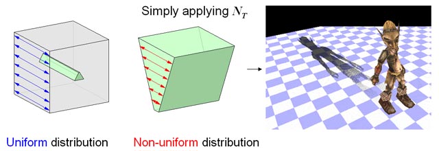
z_T of the vertex in trapezoidal space depends on the w_T. In the actual fact, the distribution of the z-values is changing over the trapezoidal shadow map so that a constant polygon offset as in the standard shadow map approach is not anymore possible to choose. The problem is that the specified polygon offset might be too high for pixels near to the eye or might be too low for pixels further away. If the polygon offset is too high it can happen that shadows are disappearing; on the other hand, if it is too low surface acne might be introduced. In the paper we suggest to maintain the z-values in the post-perspecive space of the light so that a polygon offset similar to that one in the standard shadow map approach can be found.
|
Figure: N_T affects the distribution of the z-values. The specified polygon offset is too big for areas nearby which results in shadow disappearing. By reducing the polygon offset, wrong self-shadowing would be introduced in areas further away.
|

|
| Figure: By maintaining the depth value in the post-perspective space of the light, a constant polygon offset can be specified like in the standard shadow map approach. The distribution remains uniform. |
In the following we show how the trapezoidal transformation can be implemented (using the NV_vertex_program and NV_fragment_program extension) so that severe polygon offset problems can be completely avoided. We only show here the TSM generation step, i.e. the first pass of the algorithm, because the second pass of the algorithm works in the same way (Transform the first texture coordinate to trapezoidal space and the second to the post-perspective space of the light. Then, on the fragment stage replace z_T with z_L).
light's vertex program:
!!VP1.0

# c[0-3]  : N_T
# c[8-11] : light's projection and modelview matrix
# c[12-15]: world matrix
# c[16-19]: inverse world matrix
# v[OPOS] : object position
# o[HPOS] : result vertex

# transform v[OPOS] into world space and store result in R4:
# R4 = W * v[OPOS]
DP4 R4.x, c[12], v[OPOS];
DP4 R4.y, c[13], v[OPOS];
DP4 R4.z, c[14], v[OPOS];
DP4 R4.w, c[15], v[OPOS];

# transform R4 into light's post-perspective space and store result in R1:
# R1 = P_L * C_L * (R4) = P_L * C_L * W * v[OPOS]
DP4 R1.x, c[8], R4;
DP4 R1.y, c[9], R4;
DP4 R1.z, c[10], R4;
DP4 R1.w, c[11], R4;

# store this R1 in the first texture coordinate:
# o[TEX0] = P_L * C_L * W * v[OPOS]
MOV o[TEX0], R1;

# transform R4 into trapezoidal space:
# o[HPOS] = N_T * P_L * C_L * W * v[OPOS]
DP4 o[HPOS].x, c[0], R1;
DP4 o[HPOS].y, c[1], R1;
DP4 o[HPOS].z, c[2], R1;
DP4 o[HPOS].w, c[3], R1;

MOV o[COL0], v[COL0];

END
light's fragment program:
!!FP1.0

# f[WPOS] : fragment in trapezoidal space (window position)
# f[TEX0] : fragment's position in post-perspective space of the light

RCP R0.x, f[TEX0].w;        # R0.x = 1 / w_L
MUL R1, f[TEX0], R0.x;      # R1 = (x_L/w_L, y_L/w_L, z_L/w_L, 1)

MAD R2.z, R1.z, 0.5, 0.5;   # R2.z = R1.z * 0.5 + 0.5; depth is now in the range [0;1]

MOV o[DEPR], R2.z;          # replace "z_T" with "z_L"

MOV o[COLR], f[COL0];

END
Note that for the sake of clarity we omitted in the two shaders above the calculation of a constant polygon offset which is added to the final depth value.
A wrong impression could be, that TSM works only on hardware which supports "xxx"_fragment_program. By using those simple shaders we address the polygon offset problem which is worsened because of the projective nature of N_T. (We note that other approaches use 2D/3D perspective transformations as well to increase shadow map resolution (like PSM). Therefore, addressing the polygon offset problem in other approaches fragment/vertex programs might be necessary as well. However, in our case the problem can be addressed very easily.)
If graphics hardware does not support "xxx"_fragment_program another approach can be used to "address" the polygon offset problem. Instead of a fragment program one can use a vertex program to maintain the z-value of the vertex in the post-perspecive space of the light. This is achieved by output v_T = (x_T, y_T, (z_L*w_T)/w_L, w_T), i.e. v_T = (x_T/w_T, y_T/w_T, z_L/w_L, 1) after homogeneous division. Note, this is not a general solution because this leads to a wrong interpolation in the interior of the triangles: It is correct on the vertex level but not on the pixel level. However, if the scene is sufficiently tesselated, no visible artifacts occur.
Using these shaders and the trapezoidal transformation N_T as calculated above, the display routine could roughly look like:
void display() {
	// 1st path: TSM generation


	// as described in Section 6 in the TSM paper,
	// as a first step we have to calculate a trapezoid based on the
	// eye frustum E.
	// The four vertices are stored in t_0, t_1, t_2, t_3
	calculateTrapezoid(&t_0, &t_1, &t_2, &t_3, P_L, C_L, E);

	// ...after that N_T is calculated as described above
	calculateTrapezoidalTransformation(&N_T, t_0, t_1, t_2, t_3);

	glViewport(0, 0, shadowmapWidth, shadowmapHeight);

	// Bind the above vertex program...
	glBindProgramNV(GL_VERTEX_PROGRAM_NV, vpLight);

	// ...and bind the above fragment program
	glBindProgramNV(GL_FRAGMENT_PROGRAM_NV, fpLight);

	glMatrixMode(GL_PROJECTION); // store N_T in GL_PROJECTION
	glLoadMatrixf(N_T);
	glTrackMatrixNV(GL_VERTEX_PROGRAM_NV, 0, GL_PROJECTION, GL_IDENTITY_NV);

	glMatrixMode(GL_MATRIX1_NV); // store in P_L * C_L and track in GL_MATRIX1_NV
	glLoadMatrixf(P_L);          // light's projection matrix, e.g. achieved with gluPerspective()
	glMultMatrixf(C_L);          // light's camera matrix, e.g. achieved with gluLookAt()
	glTrackMatrixNV(GL_VERTEX_PROGRAM_NV, 8, GL_MATRIX1_NV, GL_IDENTITY_NV);

	glMatrixMode(GL_MODELVIEW);  // store the modelview matrix in GL_MODELVIEW
	glLoadIdentity();
	glTrackMatrixNV(GL_VERTEX_PROGRAM_NV, 12, GL_MODELVIEW, GL_IDENTITY_NV);

	renderScene();

	// Like in the standard shadow map approach we copy the depth buffer into a texture:
	CopyDepthBufferToTexture();
	...

	// 2nd path: render scene from eye's position and project TSM texture over the scene
	...
	SwapBuffers();
}
For further enquiries/suggestions please contact tobiasmartin@t-online.de or tants@comp.nus.edu.sg. Here is a part of the source code that may help in developing the above.
version 0.99999999, 12 July, 14 July, 16 July, 1 September, 16 November, 26 November 2004, 27 Feb 2008 © NUS
This document, TSM_recipe.html, has been accessed 3071 times since 25-Jun-24 11:57:13 +08. This is the 3rd time it has been accessed today.
A total of 1628 different hosts have accessed this document in the last 722 days; your host, 216.73.217.37, has accessed it 2 times.
If you're interested, complete statistics for this document are also available, including breakdowns by top-level domain, host name, and date.