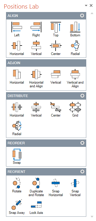
Positions Lab allows you to reposition objects on a slide with fewer steps than before. With a variety of options in the settings of each function, you can fine tune how objects are positioned on a slide.
Aligning objects
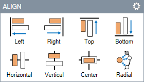
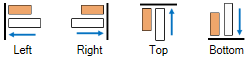
Aligning to Edges
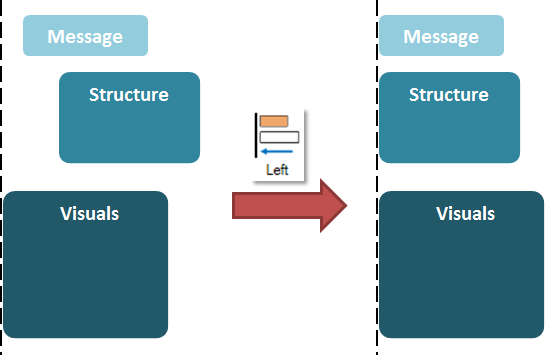
Suppose we want to position the three shapes shown below to make them overlap.
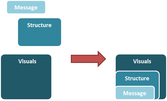
First, we click on the shape with the text "Visuals", which is the reference object we want to align to. Next, we use ctrl-click to select the rest of the objects. By clicking Align Left, we can align all other objects to the left visual edge of the "Visuals" shape as seen below.
We continue by clicking Align Bottom to align all other objects to the bottom of the "Visuals" shape.
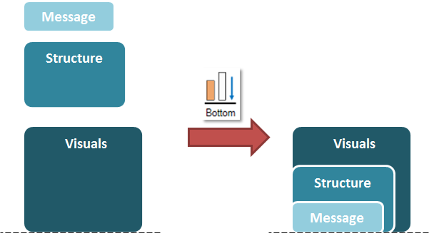
Similarly, the Align functions for Top and Right align the rest of the objects to the Top and Right of the first clicked object (the reference object) respectively.
Aligning to an Axis
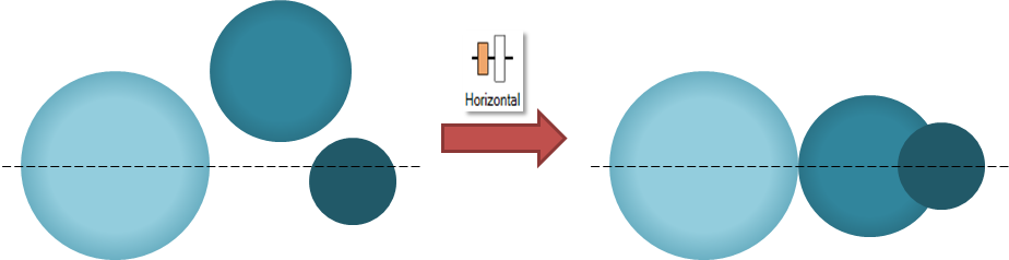
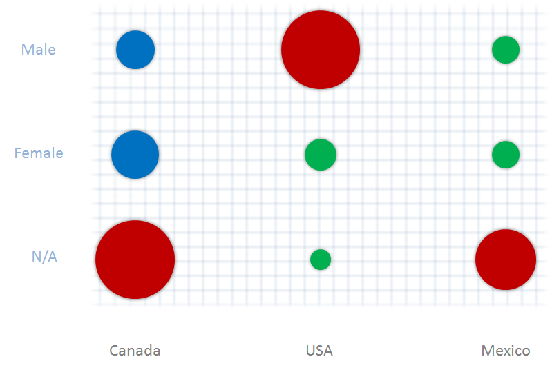
Suppose now you want to align the component objects by a particular object’s center, instead of its edges, like the one below.
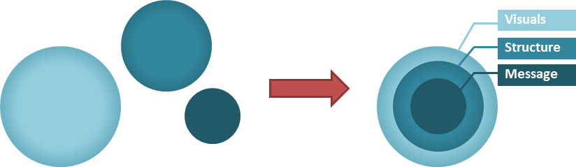
We can do this by using the Align to Axis functions.
Click to select the biggest circle as the reference object. Use ctrl-click to select the rest of the objects. Click Align Horizontal to horizontally align all other objects to the center of the reference object.
We then click Align Vertical to vertically align all other objects to the center of the reference object.
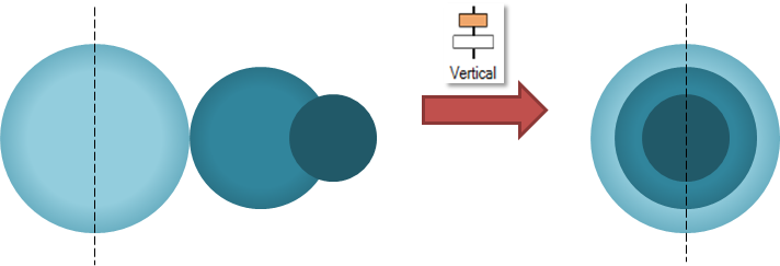
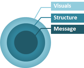
Now add in some labels to create our relationship diagram.
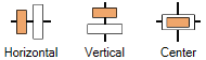
Align Center is the combination of both Align Horizontal and Align Vertical. For the previous example, we could have used Align Center to achieve the same result we wanted in just one step.
Aligning Radially

Align Radial equalizes the distance between each selected objects and the center of the reference object.
Align Radial uses the first selected object as the reference object. The center of the reference object is the origin where all distances will be calculated from. Align Radial calculates the distance between the center of the second selected object and the origin and aligns other selected objects to the same distance.
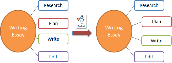
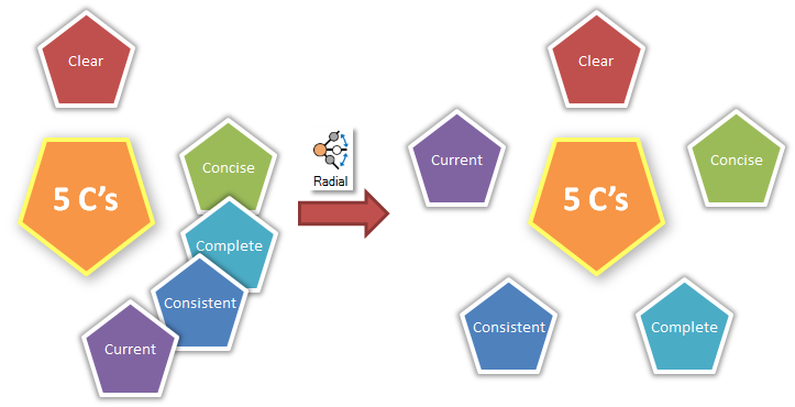
For example, we would like to create a radial list by aligning the supporting points at a fixed distance around the main topic. To do this, first select the reference object, which is the main topic. Next, select one of the supporting points to fix the alignment distance. Then, select the objects to be aligned and click Align Radial.
Align Settings
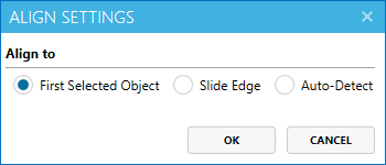
Align feature comes with several settings. Our previous examples uses the default value for the Align to options, which is First Select Object.
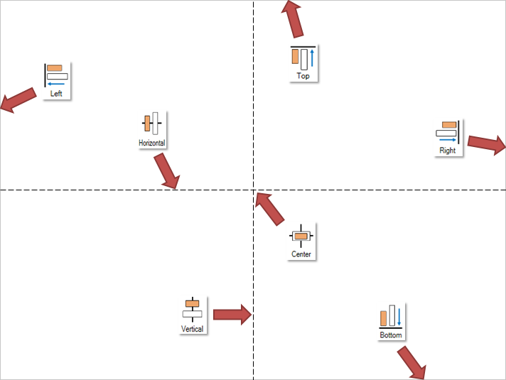
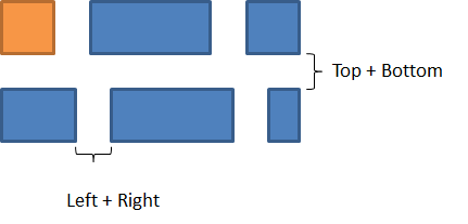
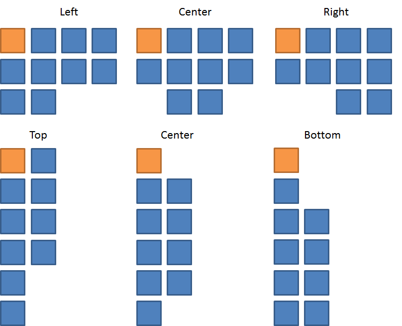
Using the Slide Edge setting will align all objects with the slide as reference. A guide on how objects will be aligned to a slide is shown below.
Auto-Detect setting will align objects similarly to PowerPoint’s default align feature. The auto-detect decides what to align to based on your selected objects.
If only one object or group is selected, it will align to the slide. This is the same as if Slide Edge is selected in the settings.
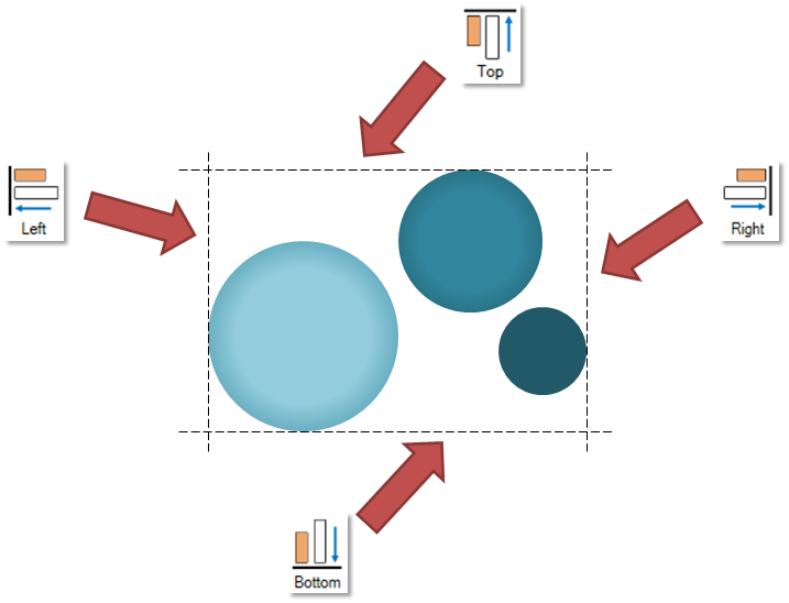
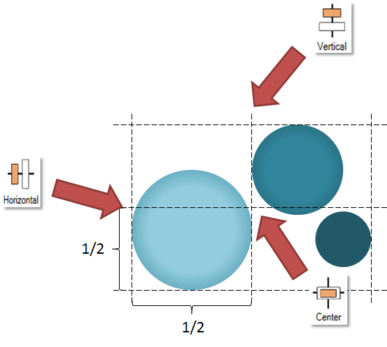
For Align to Axis, it will calculate the middle axis between the corner most objects and align the objects to the calculated middle axis as seen in the example below.
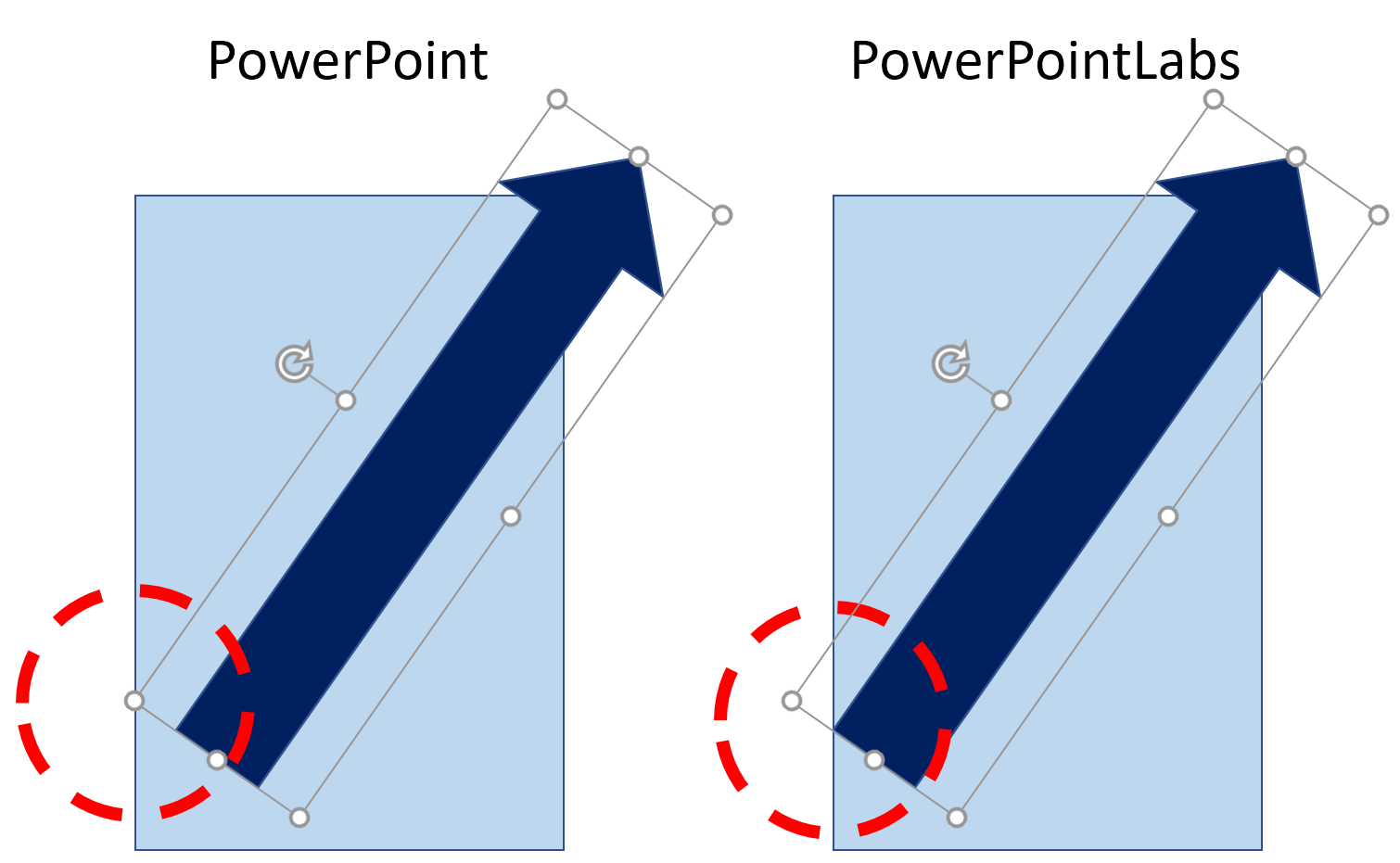
Another difference to note between Positions Lab’s Align and PowerPoint’s default align is that Positions Lab will align objects by their visual edge, whereas PowerPoint will align objects by their bounding box (the white box surrounding each object). This becomes apparent when using objects like arrows that are rotated. Below is an example of the difference when using Align left:
Note:
Align Radialdoes not use the Align settings.
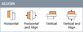
Adjoining objects
Adjoining without Aligning


Suppose, in the example below, we want to move the shapes on the left to form a timeline as shown on the right. Click to select the first object (in this case, the "IMPLEMENTATION" object) as the reference object for all other objects to adjoin to. Use ctrl-click to select the rest of the objects. Click Adjoin Vertical to get the result below.
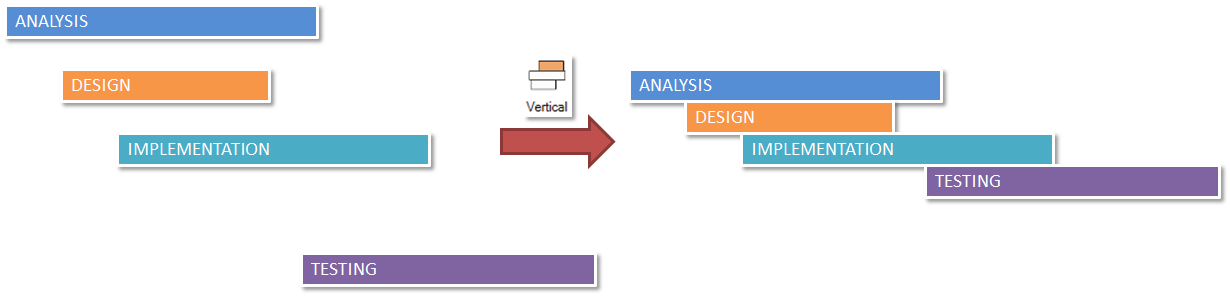
The "IMPLEMENTATION" object has not moved, while the rest of the objects moved vertically towards it in the specified direction. The first selected object is always stationary and the rest of the objects are moved such that they are adjoined to each other. For Adjoin Horizontal, the objects will only move horizontally.
Adjoining with Aligning


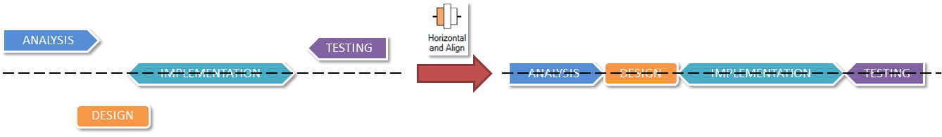
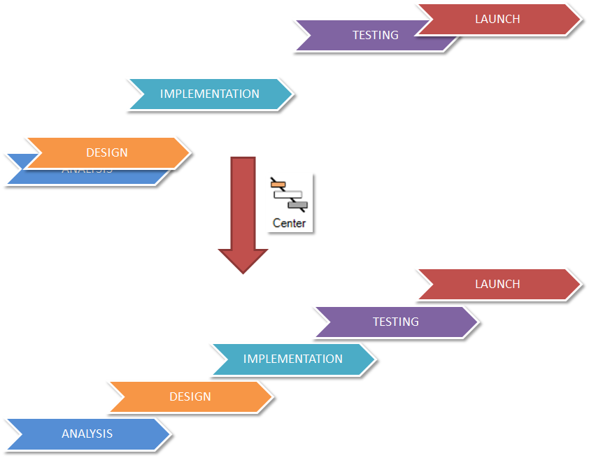
Suppose we want to create a horizontal timeline like the one below.

We can achieve this with the Adjoin Horizontal and Align feature. Click on the IMPLEMENTATION object first to make it the reference object. Use ctrl-click to select the rest of the objects. Clicking Adjoin Horizontal and Align will adjoin and align all selected shapes to the reference object’s center, as illustrated below.
Adjoin Vertical with Align adjoins and aligns selected objects to the reference object’s center. This is useful for creating pyramid diagrams like the one below.
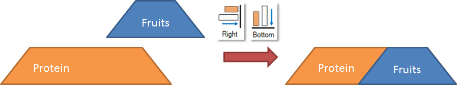
Use Align Right and Align Bottom to overlay Fruits on top of Protein. Then group them to form a single object.
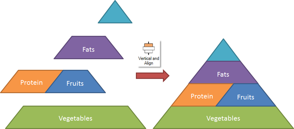
Then click on Adjoin Vertical with Align to stack the objects on top of each other, aligning them by their centers.
Distributing objects
Distribute features take a group of objects and distributes them within a specified range of space. By equalising the gaps between selected objects we can make objects look evenly spread out within the desired space.
Distribute Settings
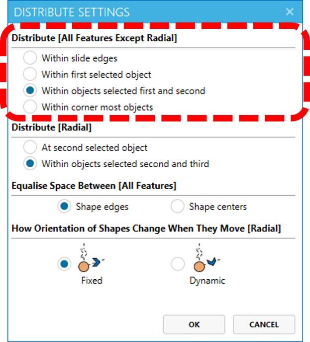
Settings have options that can customize the behaviors of the Distribute features.
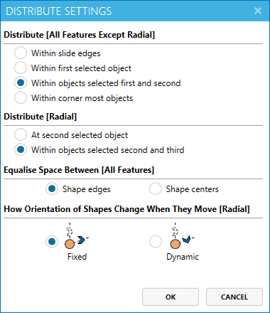
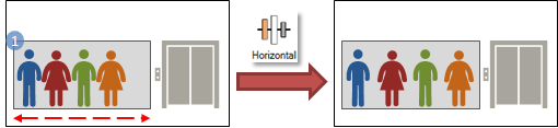
Firstly, you can decide what will the selected objects be distributed within. Distribute Horizontal, Distribute Vertical, Distribute Center and Distribute Grid use different options from Distribute Radial to detect the reference objects. By default, all distribute features except Distribute Radial work with the first two selected objects as the reference object. The remaining selected objects will then be distributed within the reference objects.
Alternative options are -- Within Slide Edges, which will distribute the selected objects evenly throughout the slide. For this mode, the order of selection is not important.
Note: "Within Slide Edges" option is not applicable to
Distribute Grid.
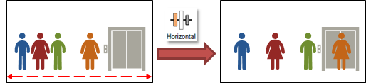
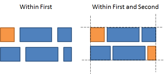
Within First Selected Object uses only one object as the reference shape. This object acts like a container, and the remaining selected objects will be evenly distributed within this container.
For example, it might be difficult to know where to position the last object to achieve the effect that was demonstrated with Within Objects Selected First and Second selected, or you only know that there is a particular segment of the slide that you want the objects to occupy. You can create a box to indicate that space, select the objects to be distributed within the space, then click on Distribute Horizontal.
Lastly, Within Corner Most Objects, which allows you to select the objects in any order and auto-detect the most sensible reference objects. Distribute feature will choose the leftmost and rightmost as the reference objects for Distribute Horizontal, and topmost and bottommost for Distribute Vertical. For Distribute Center, both sets of reference objects, which may be different, are used.
Note: "Within Corner Most Objects" option is not applicable to
Distribute Grid.
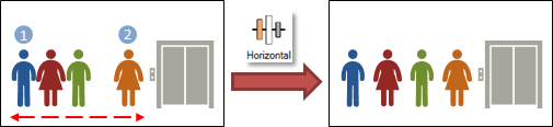
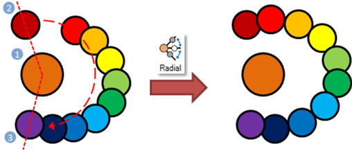
For Distribute Radial, the first selected object is the reference object. The center of the reference object is the origin where all angle will be calculated from. By default, Distribute Radial uses the option Within Objects Selected Second and Third.
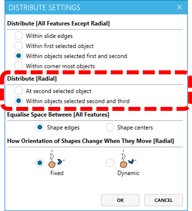
Within Objects Selected Second and Third option distributes objects evenly around the reference object within an angle starting from the second selected object to the third selected object in a clockwise manner. If you would like to distribute objects in the opposite direction instead, swap the order of selection for the second and third selected object.
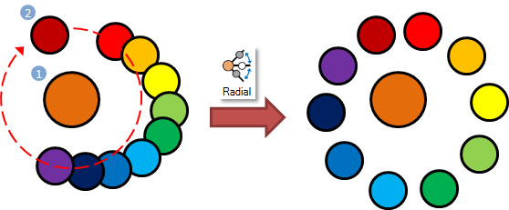
At Second Selected Object can be used to distribute objects evenly in a full circle around the reference object starting from the second selected object.
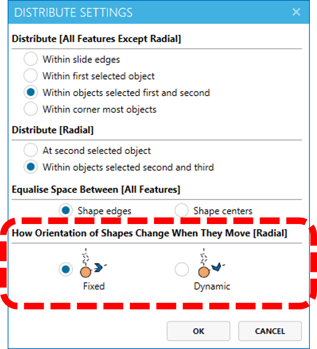
Distribute Radial moves shapes around the center of the reference object. You can choose whether the orientation of shapes changes when moving them. By default, Distribute Radial uses the option Fixed, which retains the orientation of shapes moved. Alternatively, you may select the option Dynamic to rotate shapes when they move.
Distributing Horizontally and Vertically
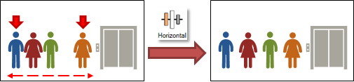
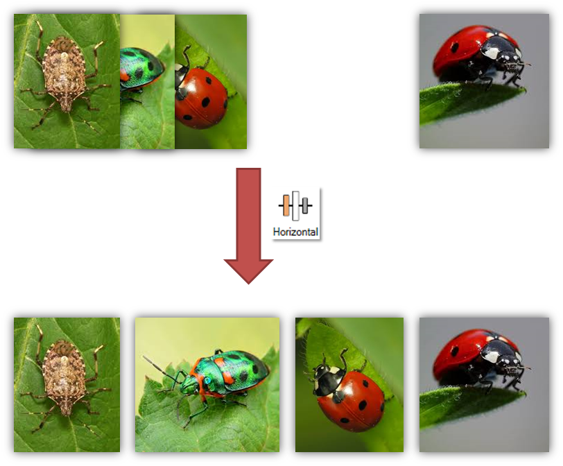
Suppose you have a number of images to display on your slide and you want them to fill up the space as evenly as possible.
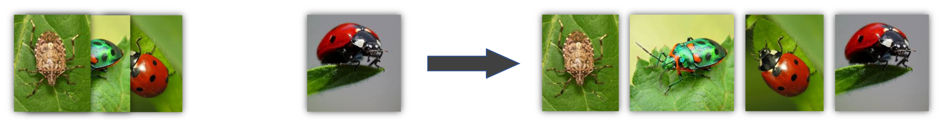
First, set the boundaries that you’d like the images to take up by placing one image at leftmost position you want your images to fill and another at the rightmost position you want the images to fill.

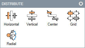
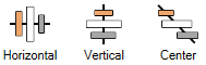
Now, ctrl-click on the leftmost image, then the rightmost image, followed by the remaining images. After that, click the Horizontal button in the DISTRIBUTE section.
Distribute Vertical also works in a similar fashion, but it only moves the objects vertically instead of only horizontally as shown in the previous example.
Distribute is also not limited to just one direction (horizontal or vertical). For example, instead of arranging the objects horizontally like the picture above, you’d now want to cascade the objects that you have.
Similarly, Distribute Center allows you to distribute a bunch of objects along the line from one object to another. In the example below, we distribute objects along the line between the Launch arrow and the Analysis arrows.
If only one image is selected, it will be aligned to the slide.
Distributing in a Grid Pattern

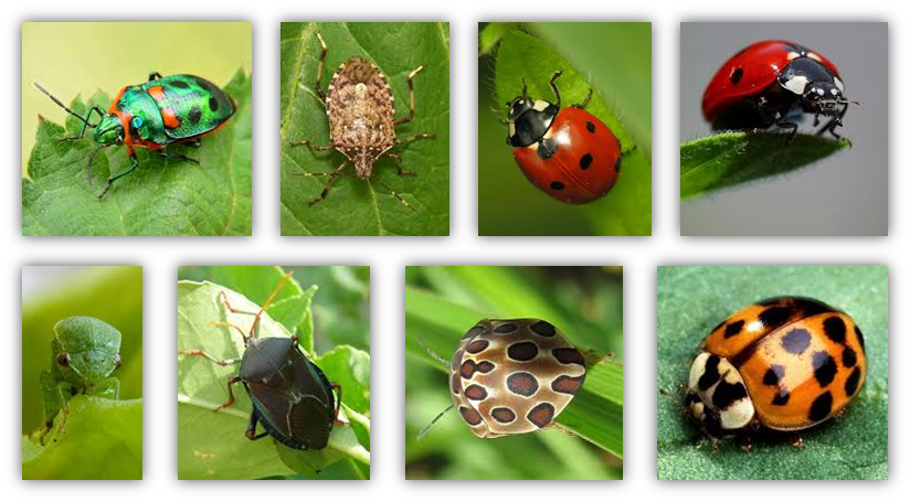
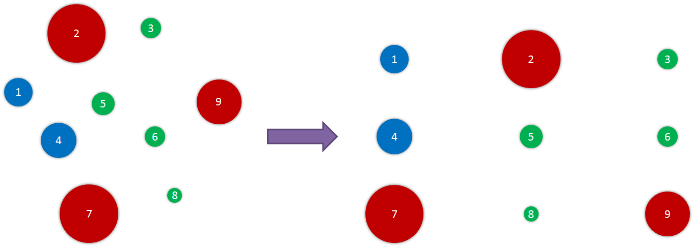
Suppose you want to present a catalogue of objects in a neat and equalised grid like the one below. You want to limit the size of the grid and ensure that each row is of equal length.
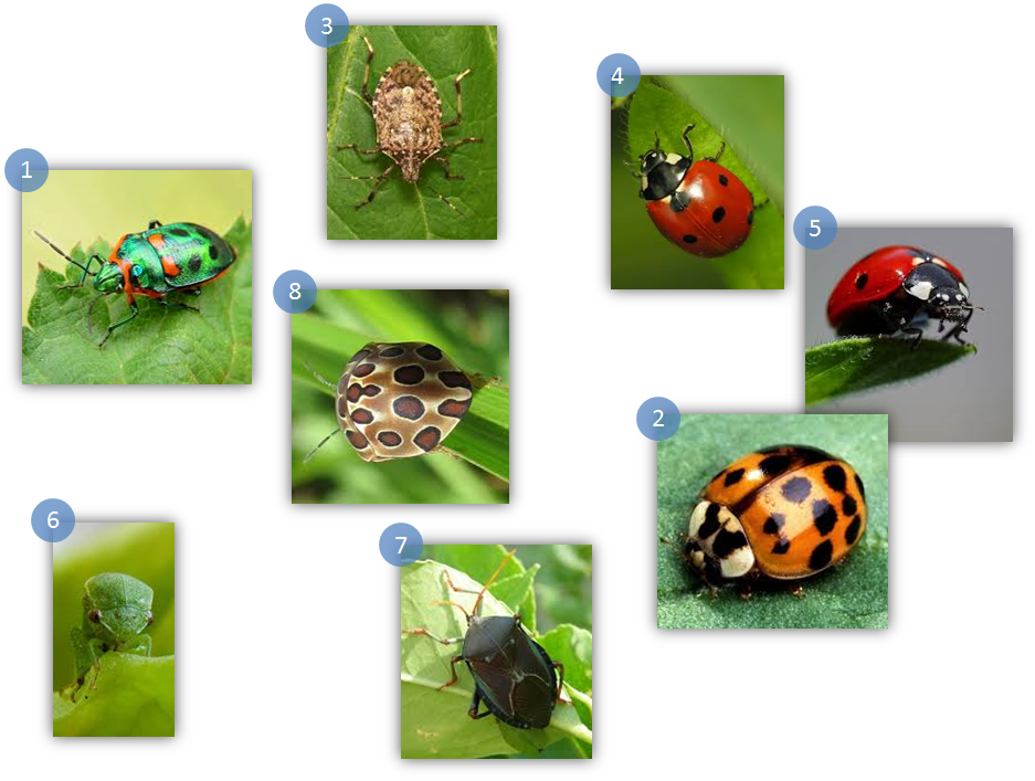
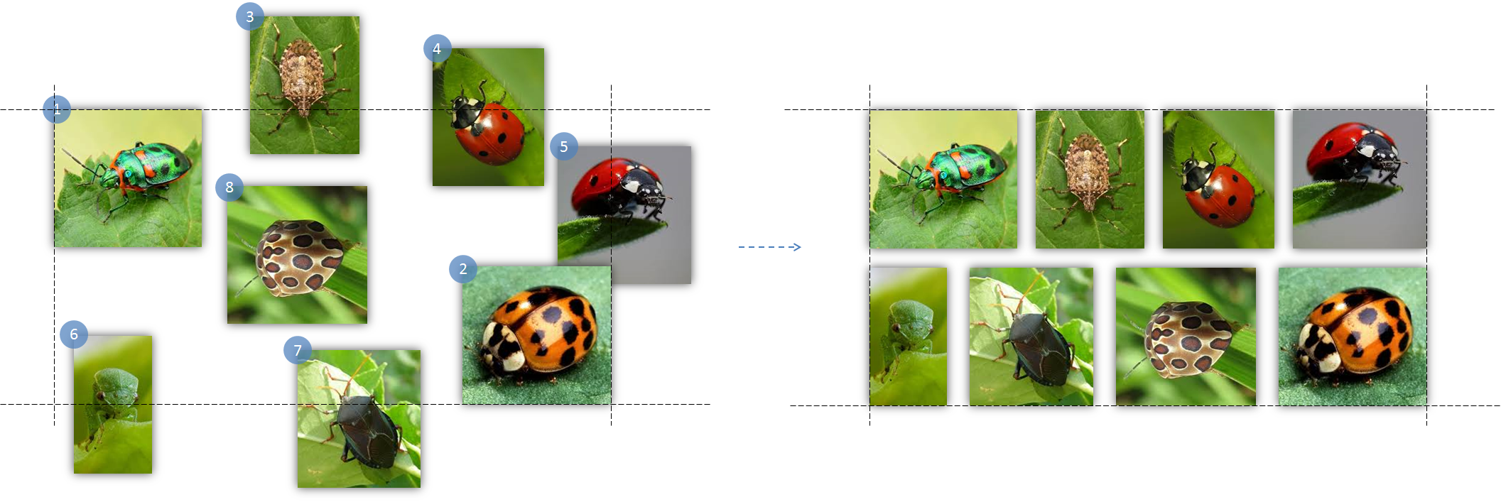
We can use the Distribute Grid function to achieve that. First, decide how large a grid you want it to be by using ctrl-click to select two objects to be the top left and bottom right corners of the grid respectively. Next, select the rest of the objects in the order you want it to appear in the row. The result may vary for different order of selections.
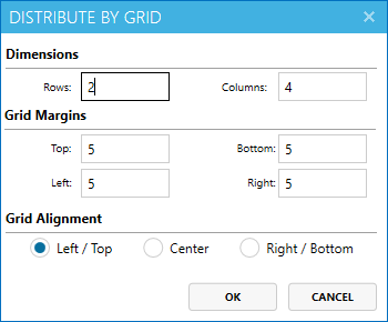
Next, click on the Distribute Grid button. A new window will appear with some settings like the one below.

Enter the number of rows or columns you wish for the grid to have. When you change the value in one box, the other value in the other box will be automatically adjusted so that the grid will always have the right number or rows and columns with regards to the number of objects selected. For this example, we can ignore the settings for Grid Margins and Grid Alignment. Once you click the OK button, you will see the result below.
Distribute Grid Settings

Distribute Grid uses settings from both the Distribute Settings window and Distribute By Grid dialog box.
Distribute
Within First Selected Object option takes the first selected object as reference object and builds the grid with that reference object as the top left corner of the grid. Within objects selected First and Second chooses the first selected object as the top left corner of the grid and the second selected object as the bottom right corner of the grid. The grid built will be contained within the boundaries of the first and second objects.
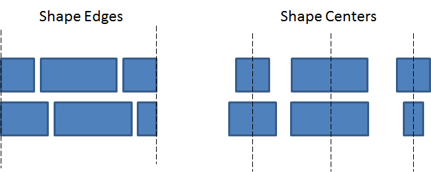
Equalise Space Between
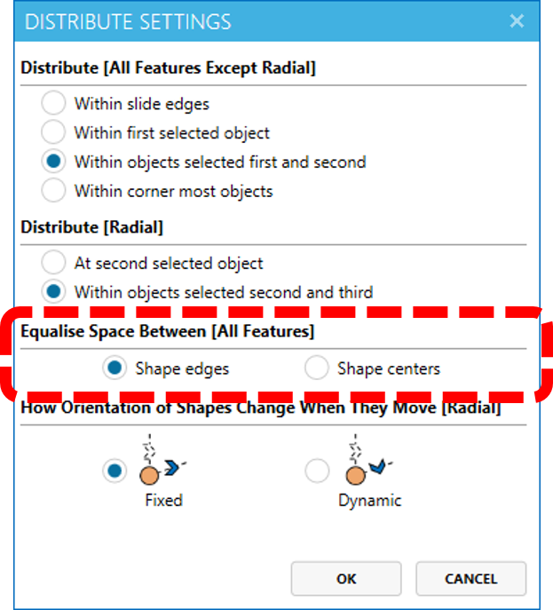
Shape edges and Shape centers options determine how the rows and columns are created. Shape edges will keep the rows (and columns if applicable) to be of the same length. Shape centers, on the other hand, align the objects in the columns by their centers.
Grid Margins
Grid Margins specify the distance between each objects.
Grid Alignment
Sometimes, the grid that is generated will have empty spaces on the last row or column. In those cases, Grid Alignment can be used to determine how the objects on the last row or column are aligned, as seen in the example below.
Interaction
The table below summarises the result of the interaction of the grid settings with each other.
| Original Shape | Distribute | Equalise Space Between | Result |
|---|---|---|---|
 |
Within First Selected Object | Shape edges |  |
| Alignment does not affect result | |||
| Shape centers |  |
||
| Alignment and Margin affect result | |||
| Within objects selected First and Second | Shape edges |  |
|
| Alignment and Margin does not affect result | |||
| Shape centers |  |
||
| Alignment and Margin does not affect result | |||
| Within Slide Edge | Does not work for `Distribute Grid` | ||
| Within corner most objects | Does not work for `Distribute Grid` | ||
Now let us demonstrate the effect of one pair of settings. Let’s say we want to create the infographic as shown below. The objects are aligned to each other by their center. In this case we can use the settings of Shape centers with either Within objects selected First and Second or Within First Selected Object. For this case, we will use Within First Selected Object.
We first use ctrl-click to select the objects in the order below.
After clicking Distribute Grid and choosing Rows: 3 and Columns: 3, click OK to order the objects in a 3x3 grid in the order that you chose. Circle 1 remains unmoved. Add the remaining background and axis to create the infographic.
Distributing Radially

Distribute Radial feature equalizes the angles between each selected object and the center of the reference object.
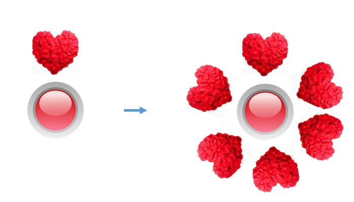
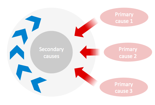
Suppose we want to create a radial diagram by distributing the sub-topics around the main topic.
First select At Second Selected Object in the Distribute Settings. Next, select the reference object, which is the main topic. Then, select the boundary objects used to determine the starting and ending points of the angle for the objects to be distributed within. Finally, select the objects to be distributed and click Distribute Radial.
If the position of the objects distributed looks slightly deviated, you can create a temporary shape, a small circle is preferred, to act as the center of the reference object and adjust to your needs. You can use Distribute Radial together with Snap Away (another feature of Positions Lab) to create pointing effects with respect to a reference object.
Note: When using
Shape edgesto equalize the space between selected objects, the objects must not cross the center of the reference object. Results may differ from expectation if that is not the case.
Reordering objects
Swap

Swap allows you to swap the positions of any 2 or more objects. By default, when more than 2 objects are selected, the objects will be swapped in a cyclic order, from left to right. After selecting a group of objects, at each click of the swap button, the objects will be swapped to the right. If there are only two objects, then they will simply swap locations.
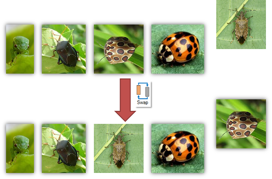
Suppose you already have perfectly aligned objects, but you wish to replace just one of them, while maintaining the original visual effects. This would be a chore, as you would have to place the new object directly on top of the old one, and then delete away the old object. With the swap functionality, it becomes a lot simpler. All you have to do is add the new object, and then select the object to be swapped out, and you’re done!
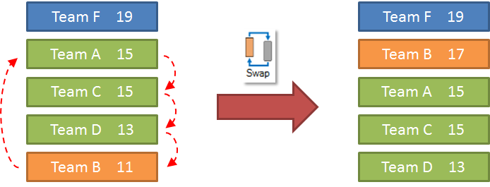
Suppose now that you are maintaining some table that keeps track of team scores and sorted in the right order. If a team suddenly overtakes a few others, it may be troublesome to rearrange them to be in the correct order. This is when cyclic swap becomes useful. An example is shown below, where Team B, originally last in the ranking, gains some points and is now second. Instead of manually moving down the teams it has overtaken and placing Team B in the correct position, you can select Teams A, C, D, and B, and apply the cyclic swap.
Reorder Settings
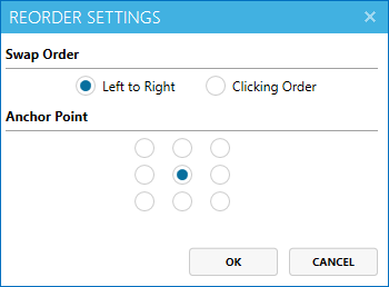
Swap Order
Swapping can be done either left to right as shown earlier, or in terms of clicking order. By default, swap will occur from left to right. For clicking order, you can simply designate the order of swap by using ctrl-click on the objects in the order that you’d like. Then, at every click of the swap button, the selected objects will be swapped in the same order.
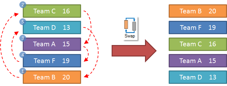
For example, let’s say again you are maintaining the scores of some teams. After a match, their points get updated as shown on the left side of the image below. In order to get them into the correct order again, you can do a swap by clicking order. First you click Team B, then Team C, then Team A, followed by Team F and lastly Team D. After clicking swap, the result is on the right, where Team B takes the place of Team C, Team C takes the place of Team A, Team A takes the place of Team F, Team F takes the place of Team D, and lastly Team D takes the place of Team B.
Anchor Point
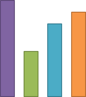
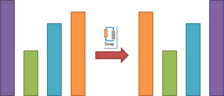
Suppose you want to reorder shapes but keep them aligned on a particular side. An example would be when you want to create a histogram like the one below. You have the bars ready but now you want to swap the orange and purple bar while keeping them aligned at the bottom.
In this case, you can select the purple and orange bar using ctrl-click and choose the anchor point to be either bottom left or right. Now click swap to get the result as shown below.
There are 9 anchor points for an object to choose how the swap function swap the shapes by. Choose the one that suits the scenario the best.
Reorienting Objects
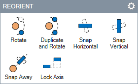
The Reorient features ease the changing of the orientation of objects.
Rotating objects around another object


Suppose you want to change the position of green arrows as follows i.e. slightly rotate them clockwise around the picture of the Sun.
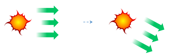
First, click the picture of the Sun (because you want to use it as the reference object) and then ctrl-click the arrows. After that, click the Rotate button. Now you can click on of the green arrow objects and drag the mouse to perform the rotation. To exit the rotate mode, click anywhere else in the slide.
Note: Instead of using the dragging the mouse to rotate objects, you can press
Up arroworLeft arrowkey to rotate anti-clockwise andDown arroworRight arrowkey to rotate clockwise.
You can also press ctrl-arrow keys to rotate slightly in the specified direction. Once you’re done rotating the shapes, simply click anywhere that is not within the selected shapes and the rotate mode will come to an end.
Duplicate and Rotate works similar to the Rotate feature above except that it rotates a duplicate of the objects being rotated i.e. originals remain intact.
Snap objects to Horizontal/Vertical orientation
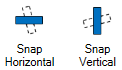
Snap Horizontal and Snap Vertical rotates objects to vertical and horizontal orientation.
Suppose you had multiple arrows that were pointing at an angle, and you now wish for them to point horizontally, you can then select all these arrows and apply the snap horizontal function.
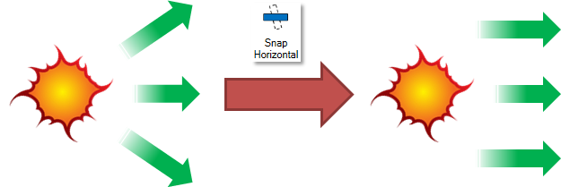
Snap Vertical works similarly, except that the objects will be vertical, instead of horizontal.
Snap Away

Snap to/away allows you to reorient objects to point away from a reference object.
Suppose you want to reorient the green arrows to point away from the picture of the Sun.
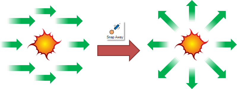
Select the Sun, then ctrl-click to select the green arrows and click the Snap Away button. You can click the button multiple times to get different orientations relative to the reference object. For example, the blue arrows and red arrows in the picture below.
Moving Objects Strictly Vertically/Horizontally

Suppose you want to move the shape B away from A without changing its vertical alignment.
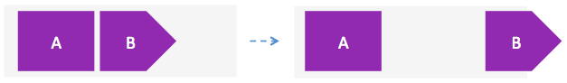
Select B and click on the Lock Axis button. Now, you can use the mouse to move B and it will move only horizontally or only vertically, but not both. That way, you can get it to move horizontally without changing the vertical alignment or vice versa.
To come out of the lock axis mode, click on the Lock Axis button again or click on some other area on the slide.
Reorient Settings
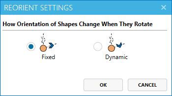
The settings is used for Rotate and Duplicate and Rotate. They work very similar to those under the DISTRIBUTE SETTINGS.
Previewing Position Lab Features
You can preview Positions Lab features by hovering over the buttons while holding on to the shift key.
Note: Preview is not applicable to Distribute Grid, Rotate and Lock Axis.