Instruction Set Architecture
We take a quick detour to see other instruction set architecture (ISA). Some of the topics here may be similar to the topic introduced when we talk about MIPS but may be generalised further to include other architecture.
To illustrate, we will first tell you about one of the most famous battles in the design philosophies for ISA. There are two camps here.
| CISC | RISC | |
|---|---|---|
| Name | Complex Instruction Set Computer | Reduced Instruction Set Computer |
| Example | x86-32, IA32 | MIPS, ARM |
| Advantages | Smaller program size, especially if memory is premium | Small and simple instruction set, easier to build/optimise hardware |
| Disadvantages | Complex processor implementation, difficult hardware optimisation | Burden on software to compile efficiently |
We will not be comparing those two. Instead, we will discuss the 5 design concepts in ISA design.
- Data Storage
- Memory Addressing Modes
- Operations in the Instruction Set
- Instruction Formats
- Encoding the Instruction Set
Objective
Concept #1: Data Storage
Modern computers employe the von Neumann architecture for which data and program are stored in memory. However, in the case of processors, storage architecture concerns more with:
- Where do we store the operands so that the computation can be performed?
- Where do we store the computation result afterwards?
- How do we specify the operands?
Some of the major storage architecture includes:
- Stack Architecture: Operands are implicitly on top of the stack.
- Examples: Python bytecode assumes stack architecture.
- Accumulator Architecture: One operand is implicitly in the accumulator (a special register).
- Examples: IBM 701, DEC PDP-8.
-
General-Purpose Register Architecture (GPR): Only explicit operands. There are two major sub-architecture:
- Register-Memory Architecture: One operand in memory.
- Examples: Motorola 68000, Intel 80386.
-
Register-Register Architecture: All operands in register. Also called load-store architecture.
- Examples: MIPS, DEC Alpha.
- Register-Memory Architecture: One operand in memory.
-
Memory-Memory Architecture: All operands in memory.
- Examples: DEC VAX.
C = A + B
We will illustrate the difference between the storage architecture by using the example of C = A + B and how each storage architecture perform this computation assuming that all the values are currently in a variable which is mapped to a memory location.
Do NOT Sort
For obvious reason, do not sort. If you do so, the order of the operations will not be in the correct order. You should reload the page to get the original order.
| Stack | Accumulator | Register (Load-Store) | Memory-Memory |
|---|---|---|---|
Push A |
Load A |
Load R1, A |
Add C, A, B |
Push B |
Add B |
Load R2, B |
|
Add |
Store C |
Add R3, R2, R1 |
|
Pop C |
Store R3, C |
Visually, we can represent them as follows:
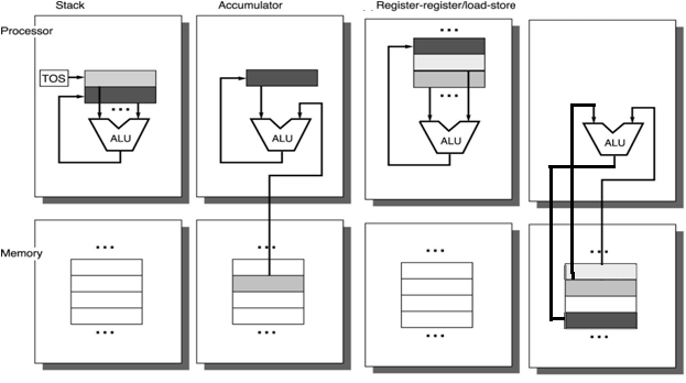
The most common storage design for modern processor is the general-purpose register (GPR). This includes many of the RISC processors (e.g., MIPS and ARM processors) which typically use register-register (i.e., load/store) architecture. On the other hand, CISC processors (e.g., IA32) use a mixture of register-register and register-memory architecture.
Concept #2: Memory Addressing Mode
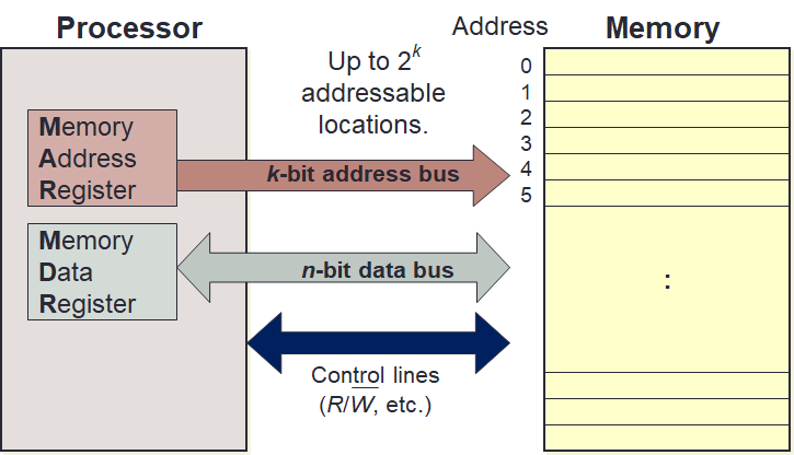
We are concerned with memory locations and addresses, the addressing modes as well as the memory content.
Memory Address
Given k-bit address, the address space is of size 2k. Each memory transfer consists of one word of n bits.
Memory Content: Endianness
Endianness is concerned with the relative ordering of the bytes in a multiple-byte word stored in memory. This is another major battle in the design philosophies.
The name comes from the root-word "end"1. In particular, which end should be in front. In other words, whether the most significant byte (i.e., big-end) should be at the lowest address or should it be the least significant byte (i.e., little-end). Note that here we order the byte and not the bit. There are two major camps here:
| Big-Endian | Little-Endian | |
|---|---|---|
| Order | Most significant byte stored in lowest address (big-end) | Least significant byte stored in lowest address (little-end) |
| Processor | IBM 360/370, Motorola 6800, MIPS, SPARC | Intel 80x86, DEC VAX, DEC Alpha |
| Example | 0xDE AD BE EF is stored as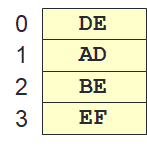 |
0xDE AD BE EF is stored as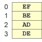 |
Addressing Modes
Addressing mode is the ways to specify an operand in an assembly language. In MIPS, there are only 3 addressing modes:
- Register: Operand is in a register (e.g.,
add $t1, $t2, $t3). - Immediate: Operand is specified in the instruction directly (e.g.,
addi $t1, $t2, 98). - Displacement: Operand is in memory with address calculated as
Base + Offset(e.g.,lw $t1, 20($t2)).
There are, however, other addressing modes summarised below:
| Addressing Mode | Example | Meaning |
|---|---|---|
| Register | Add R4, R3 |
R4 ↤ R4 + R3 |
| Immediate | Add R4, #3 |
R4 ↤ R4 + 3 |
| Displacement | Add R4, 100(R1) |
R4 ↤ R4 + M[100+R1] |
| Register Indirect | Add R4, (R1) |
R4 ↤ R4 + M[R1] |
| Indexed / Base | Add R3, (R1 + R2) |
R3 ↤ R3 + M[R1 + R2] |
| Direct or Absolute | Add R1, (1001) |
R1 ↤ R1 + M[1001] |
| Memory Indirect | Add R1, @R3 |
R1 ↤ R1 + M[M[R3]] |
| Auto-Increment | Add R1, (R2)+ |
R1 ↤ R1+M[R2]; R2 ↤ R2+d |
| Auto-Decrement | Add R1, -(R2) |
R2 ↤ R2-d; R1 ↤ R1+M[R2] |
| Scaled | Add R1, 100(R2)[R3] |
R1 ↤ R1 + M[100+R2+R3×d] |
Concept #3: Operations in Insturctions Set
There are some standard operations that are common to most modern processors:
| Operations | Examples |
|---|---|
| Data Movement | load (from memory) store (to memory) memory-to-memory move register-to-register move input (from I/O device) output (to I/O device) push (to stack) pop (_from stack) |
| Arithmetic | the operations typically applicable to both integer and floating point add subtract multiply divide |
| Shift | shift left shift right rotate left rotate right |
| Logical | not and or set clear |
| Control Flow | jump (unconditional) branch (conditional) |
| Subroutine Linkage | call (to procedure) return (from procedure) |
| Interrupt | trap return |
| Synchronisation | test & set (atomic r-m-w) |
| String | search move compare |
| Graphics | pixel and vertex operations compression/decompression |
Additionally, we can look at the frequently used instructions. The idea is that since these instructions are frequently used, it makes sense to make these instructions fast!
Make the common case fast!
| Rank | Integer Instructions | Average % |
|---|---|---|
| 1 | Load | 22% |
| 2 | Conditional Branch | 20% |
| 3 | Compare | 16% |
| 4 | Store | 12% |
| 5 | Add | 8% |
| 6 | Bitwise AND | 6% |
| 7 | Sub | 5% |
| 8 | Move Register to Register | 4% |
| 9 | Procedure Call | 1% |
| 10 | Return | 1% |
| Total | 96% |
Concept #4: Instruction Formats
We are concerned with instruction length as well as instruction fields. In particular, for instruction fields, we are interested in the type and size of operands.
Instruction Length
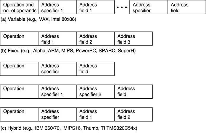
-
Variable-Length Instructions
-
Examples:
- Intel 80x86: Instructions vary from 1 to 17 bytes long.
- Digital VAX: Instructions vary from 1 to 54 bytes long.
-
Require multi-step fetch and decode.
- Allow for more flexible (but complex) and compact instruction set.
-
-
Fixed-Length Instructions
-
Examples:
- MIPS, PowerPC: Instructions are 4 bytes long.
-
Allow for easy fetch and decode.
- Simplify pipelining and parallelism.
- Instruction bits are scarce.
-
-
Hybrid Instructions: A mix of variable- and fixed-length instructions.
Instruction length is closely related to the encoding.
Instruction Fields
An instruction consists of:
Opcode: Unique code to specify the desired operation.Operands: Zero or more additional information needed for the operation.
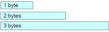
The operation designates the type and size of the operands. Typical type and size are as follows2:
- Characters: 8 bits.
- Half-Word: 16 bits.
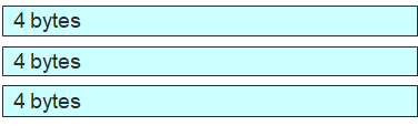
- Word: 32 bits.
- Single-Precision Floating Point: 1 word.
- Double-Precision Floating Point: 2 words.
Given the typical size above, any new 32-bit architectures are expected to support 8-, 16- and 32-bit integer as well as 32- and 64-bit floating point operations. Additionally, a 64-bit architecture would need to support 64-bit integers as well.
Concept #5: Encoding the Instruction Set
Here, we are interested in how the instructions are represented in binary format for execution by the processor. This is the assembly process.
There are certain issues that we need to think about when we are designing the instruction set. Some of the common issues include the code size, speed (or performance) and design complexity. We further need to decide the following:
- Number of registers.
- Number of addressing modes.
- Number of operands in an instruction.
We generally have 3 encoding choices that are closely related to the instruction length.
Encoding
The fixed-length instruction presents a much more interesting challenge.
We will need to fit multiple sets of instruction types into the same limited number of bits.
To do that, we will need to work with the most constrained instruction types first.
There is also the expanding opcode scheme that allows the opcode to have variable length for different instructions.
We have encountered this before with the use of funct field.
This is a good way to maximize the instruction bits.
Although there are some formula that can be used, the formula depends largely on the constraints that we have. As such, we will illustrate the encoding with examples instead.
Maximum Number of Instructions
Consider a 16-bit fixed length instructions with 2 types of instructions.
- Type-A: 2 operands, each operand is 5-bit.
- Type-B: 1 operand, the operand is still 5-bit.
We want to answer the following question:
What is the maximum number of unique instructions that can be encoded assuming that each type must have at least 1 instruction?
We will follow the design principles by keeping the common part common. The actual ordering does not actually matter, but we only need to line up the different fields. One possible alignment is shown below:
| Types | 6 Bits | 5 Bits | 5 Bits |
|---|---|---|---|
| A | opcode |
Operand |
Operand |
| B | opcode |
Operand |
unused |
We can see from this design that the maximum total number of instructions is 26 of 64 instructions.
This is because the opcode is 6-bit long.
This is because we can only use the opcode to differentiate the type of instructions.
This leads to the most obvious problem. 5-bits in type-B instructions are wasted because it is not used. A solution to this is to use expanding opcode scheme by using the unused bits as additional opcodes. This is what we are going to discuss in the next example.
The basic idea is to extend th opcode for type-B instructions to 11 bits by using the previously unused bits.
There are many possible alignments.
We will use the following alignment which differ slightly from the lecture notes but it highlights the similarity to the previous scheme.
| Types | 6 Bits | 5 Bits | 5 Bits |
|---|---|---|---|
| A | opcode |
Operand |
Operand |
| B | opcode |
Operand |
opcode2 |
We use the name opcode2 to show that this is also an opcode but the expanded version.
To determine the maximum number of different instructions that we can have, we need to first be able to distinguish between type-A and type-B instructions.
There are two possibilities:
-
Minimise Type-A Instruction
- In this case, we can simply assign 1
opcodefor type-A (e.g.,000000). - Then, we can use the
opcodefrom000001to111111for type-B.- But type-B as
opcode2which can range from00000to11111.
- But type-B as
- This leads to a total of:
- Type-A:
- 1 instruction with
opcode000000.
- 1 instruction with
- Type-B:
- For each
opcodein the range of000001to111111(i.e., 26-1 instructions). - We have
opcode2in the range of00000to11111(i.e., 25 instructions). - Total is 26-1 × 25 = 2016
- For each
- Grand total = 2016 + 1 = 2017
- Type-A:
- In this case, we can simply assign 1
-
Maximise Type-A Instruction
- In this case, we assign 26-1 instructions to type-A with the range from
000001to111111. - We need 1
opcode(e.g.,000000) for type-B but we still have 25 instructions fromopcode2in the range of00000to11111. - This leads to a total of:
- Type-A:
- 26-1 instructions with
opcodefrom000001to111111.
- 26-1 instructions with
- Type-B:
- 25 instructions with
opcode2from00000to11111.
- 25 instructions with
- Grand total = 63 + 32 = 95
- Type-A:
- In this case, we assign 26-1 instructions to type-A with the range from
Obviously the first possibility gives more possible instructions.
Minimum Number of Instruction
If the question is about the minimum number of instruction such that the encoding space is completely utilised (i.e., no more instructions can be accommodated), then the second possibility gives us this value.
So, the maximum number of instruction is 2017 using the expanding opcode scheme.
Expanding Opcode Design
Consider a 36-bit fixed length instructions with 3 types of instructions:
- Type-A: 3 operands (2 addresses + 1 register number)
- Type-B: 2 operands (1 address + 1 register number)
- Type-C: 0 operand
The operands take the following number of bits:
- Address: 15 bits.
- Register Number: 3 bits.
Additionally, you are asked that each type of instructions must have at least the following number of instructions:
- Type-A: 7 instructions
- Type-B: 500 instructions
- Type-C: 50 instructions
One possible answer is as follows:
| Types | 3 Bits | 15 Bits | 15 Bits | 3 Bits |
|---|---|---|---|---|
| A | opcode |
Address |
Address |
Register |
| B | opcode |
opcode2 |
Address |
Register |
| C | opcode |
opcode2 |
unused | unused |
More specifically, we can specify the following opcode and opcode2:
| Types | 3 Bits | 15 Bits |
|---|---|---|
| A | 000 - 110 |
|
| B | 111 |
000000 000000000 - 000000 111111111 (29 = 512) |
| C | 111 |
000001 000000000 - 111111 000000000 (26-1 = 63) |
First, we will need to identify how many bits are available for opcode and possibly for expanded opcode (e.g., opcode2).
To find this number, we simply look at the most restrictive instruction.
In this case, it is type-A because it requires 3 operands.
Since type-A instruction requires 2 addresses and 1 register number, we can calculate the remaining bits.
| Opcode Bits | |
|---|---|
1 2 3 4 | |
Secondly, we may want to find a layout the bits for type-A instruction and match the layout for the common parts of type-B and type-C instructions. Since technically the layout can be anything we want, this step can actually be abstracted away. But it is still a very useful step. A possible layout is shown below:
| Types | 3 Bits | 15 Bits | 15 Bits | 3 Bits |
|---|---|---|---|---|
| A | opcode |
Address |
Address |
Register |
| B | opcode |
opcode2 |
Address |
Register |
| C | opcode |
opcode2 |
opcode3 |
opcode4 |
Note that since type-C has no operand, we can have 4 kinds of opcodes (i.e., opcode, opcode2, opcode3 and opcode4).
Lastly, we find the possible opcodes.
A suggestion is to start from the most restrictive instructions with the fewest number of bits for the opcode.
Since we require 7 type-A instructions, we can assign any 7 opcode.
Let us simply choose 000 - 110.
This means that we only have 1 remaining opcode for both type-B and type-C.
Luckily, that is enough since we have opcode2, opcode3 and opcode4.
At this point, we can easily give 1 value from opcode2 for type-C since there are still opcode3 and opcode4 that make up to 218 possible instructions.
This would still give us 215-1 (the -1 is from giving 1 value from opcode2 for type-C) for type-B instruction.
The answer we gave in the "Answer" tab is a simple optimisation.
Past Midterm/Exam Questions
A certain machine has 12-bit instructions and 4-bit addresses. Some instructions have one address and others have two. Both types of instructions exist in the machine
-
What is the maximum number of instructions with one address?
(a) 15
(b) 16
(c) 240
(d) 256
None of the above -
What is the minimum total number of instructions, assuming the encoding space is completely utilised (that is, no more instructions can be accommodated)?
(a) 31
(b) 32
(c) 48
(d) 256
None of the above
-
c
Steps
Bit layout (total is 12 bits so
opcodeis 4 bits):Types 4 Bits 4 Bits 4 Bits A opcodeAddressAddressB opcodeopcode2AddressMaximise type-B by minimising type-A. Give only 1
opcodefor type-A (e.g.,0000). So, we can have the followingopcodefor type-B:0001-1111(i.e., 24-1 = 15). For each of those, we can have the followingopcode2for type-B:0000-1111(i.e., 24 = 16). This gives a total for type-B to be 15 × 16 = 240. -
a
Steps
Bit layout (total is 12 bits so
opcodeis 4 bits):Types 4 Bits 4 Bits 4 Bits A opcodeAddressAddressB opcodeopcode2AddressMinimise total by maximising type-A. Give only 1
opcodefor type-B (e.g.,0000). So, we can have the followingopcodefor type-A:0001-1111(i.e., 24-1 = 15). We can still have the followingopcode2for type-B:0000-1111(i.e., 24 = 16). This gives a total of 15 + 16 = 31.
-
The name was introduced by Danny Cohen in 1980 in Internet Engineering Note #137. It was borrowed from the novel Gulliver's Travels (1726). In the novel, the term describes two opposing factions in the nation of Lilliput. The big-endian broke their boiled eggs at the big end. They rebelled against the King who demanded his subject to break their eggs at the little end. ↩
-
The actual size may depend on the the processor themselves. The values given here are common for 32-bit processors. A word is typically defined to be the same length as processor line, in this case it's 32 bits. ↩