Control Signal
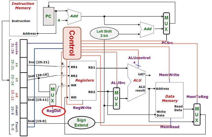
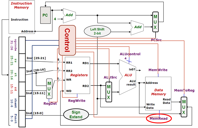
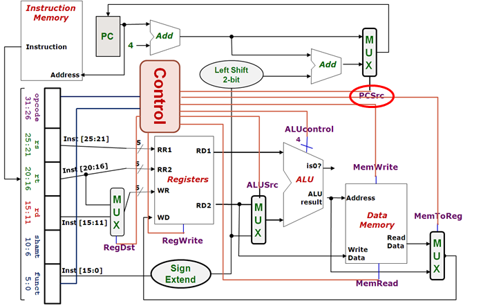
We start with the complete datapath below. Can you identify the control signals? Hint: they are colored blue.
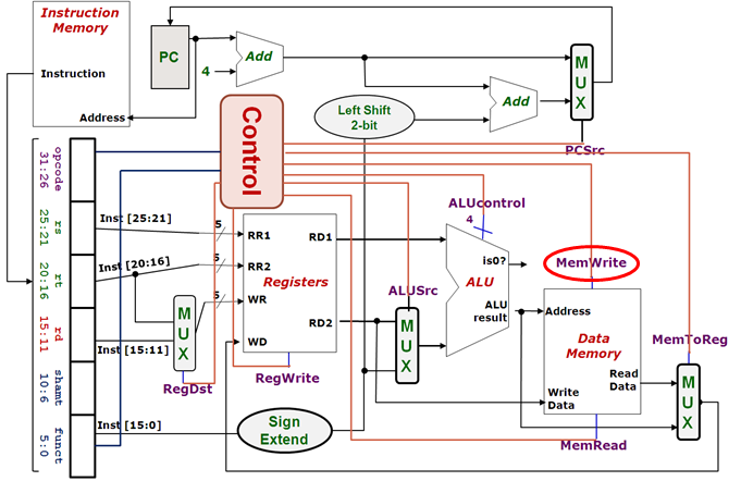
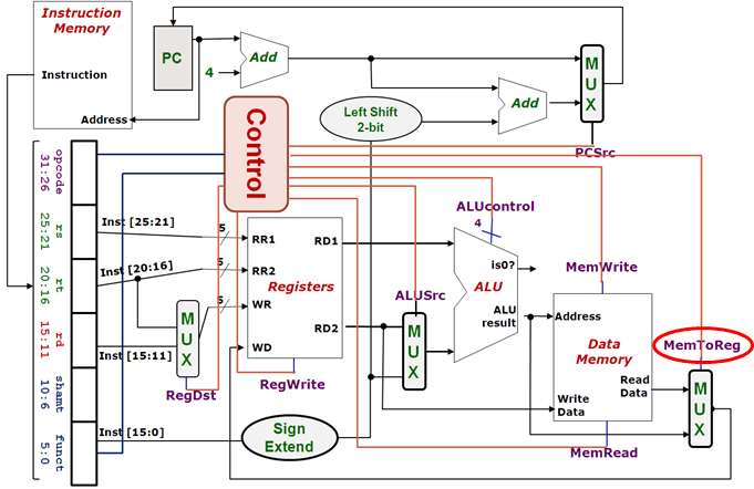
Complete Datapath
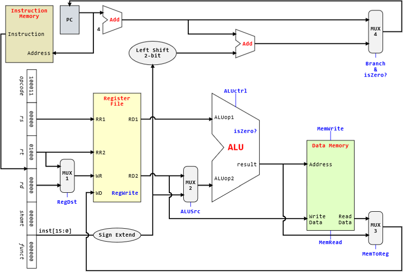
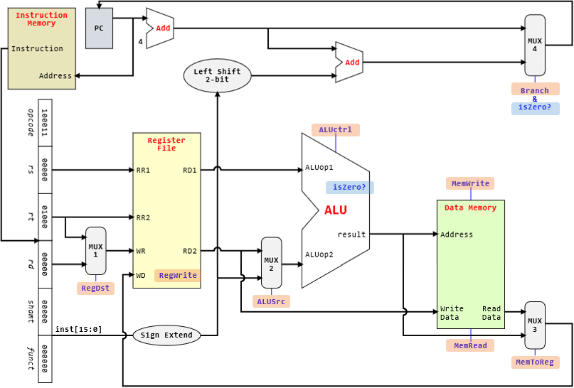
There are 8 identifier control signals.
Control Signals
| Signal | Stage | Purpose | Values |
|---|---|---|---|
RegDst |
Decode | Select the destination register number | ∘ 0: $rt ∘ 1: $rd |
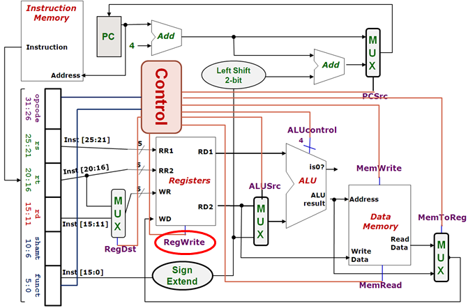
RegWrite |
Decode/Writeback | Enable writing of register | ∘ 0: no write ∘ 1: write |
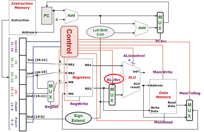
ALUSrc |
ALU | Select the 2nd operand for ALU | ∘ 0: $rt ∘ 1: immediate |
ALUcontrol |
ALU | Select the operation to be performed by the ALU | see ALUcontrol table |
MemRead |
Memory | Enable reading of data memory | ∘ 0: no read ∘ 1: read1 |
MemWrite |
Memory | Enable writing of data memory | ∘ 0: no write ∘ 1: write1 |
MemToReg |
Writeback | Select the result to be written back to register file | ∘ 0: ALU result ∘ 1: memory data2 |
Branch3 |
Memory/Writeback | Select the next $PC value |
∘ 0: $PC+4 ∘ 1: ($PC+4)+(immediate×4) |
ALUcontrol
| ALUcontrol | Function |
|---|---|
| 0000 | and |
| 0001 | or |
| 0010 | add |
| 0110 | sub |
| 0111 | slt |
| 1100 | nor |
Supported Instructions
Before we start, we will need to further restrict the instructions that can be supported so that the processor will be as simple as possible while maintaining full capability of the processor assuming that we have powerful compiler to generate the necessary instructions.
It is actually quite "simple" to create a powerful machine that is Turing complete. All we need are three kinds of instructions:
- Sequence: This is automatic as the sequence is top to bottom.
- Selection: Can be done using
beq. - Selection: Can also be done using
beqbut jump upwards.
To have practically unlimited memory, we also want to have load/store operations. As such, we will only support the following instructions:
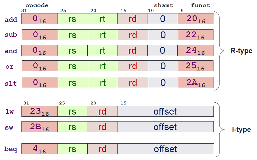
| Instruction | Code |
|---|---|
| Addition | add $rd, $rs, $rt |
| Subtraction | sub $rd, $rs, $rt |
| Bitwise AND | and $rd, $rs, $rt |
| Bitwise OR | or $rd, $rs, $rt |
| Set on Less Than | slt $rd, $rs, $rt |
| Branch on Equal | beq $rd, $rs, label |
| Load Word | lw $rt, offset($rs) |
| Store Word | sw $rt, offset($rs) |
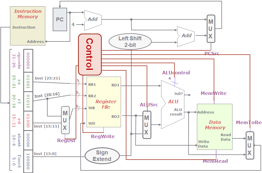
Control Unit
We are now going to generate the control signals.
The control signals are generated based on the instruction to be executed.
This can be found by looking at the opcode field.
But for R-format instructions, we will also need to look at the funct field.
This is where fixed-length instructions really shines, these fields are located in a fixed location.
opcode:Inst[26:31]funct:Inst[0:5]
R-Format
One way to look at this is to see what are the control signals we need for each instruction. For R-format instructions, we can see that we will need the following values for the control signals:
| Signal | Value | Reason |
|---|---|---|
RegDst |
1 |
Destination register is $rd (Inst[11:15]) |
RegWrite |
1 |
We need to write into the register |
ALUSrc |
0 |
2nd ALU operands comes from Register File |
ALUcontrol |
depend | Depends on the actual operation to be performed by ALU |
MemRead |
0 |
No need to read from meory |
MemWrite |
0 |
No ened to write into memory |
MemToReg |
0 |
Select from ALU result to be written back (remember, multiplexer is flipped) |
Branch |
0 |
No need to branch, next value of $PC is $PC + 4 |
MemToReg
Another way to look at this is to see what is the value of a particular control signal given all supported instructions.
For the MemToReg control signals (remember, this is flipped), we can see that we will need to the following values:
| Instruction | Value | Reason |
|---|---|---|
| R-Format | 0 |
Choose from ALU result |
lw |
1 |
Choose from data read from memory |
sw |
X |
Does not matter, can be any value |
beq |
X |
Does not matter, can be any value |
So how are we going to generate these signals?
We will try to imagine having a control unit.
We will take note of the instruction subset to be implemented as well as the opcode and funct.
By observing each of the signal, we can create a "truth table".
Lastly, we will design the control unit using logic gates.
There are certain techniques and/or tricks that are going to be covered in more details in the second half of the semester.
So, for now, we will simply note that many of the logic gates can be abstracted as a function.
Details
- False (
0):Write Register=Inst[20:16] - True (
1):Write Register=Inst[15:11]
- False (
0): No register write - True (
1): New value will be written
- False (
0):ALUop2=Read Data 2 - True (
1):ALUop2=sign_extend(Inst[15:0])
- False (
0): Not performing memory read access - True (
1): Read memory using ALUresultasAddress
- False (
0): Not performing memory write operation - True (
1): Write to memory atAddress(from ALUresult) with data fromRead Data 2
- True (
1): RegisterWrite Data= MemoryRead Data - False (
0): RegisterWrite Data= ALUresult
- False (
0):$PC' = $PC+4 - True (
1):$PC' = ($PC+4)+(immediate×4)
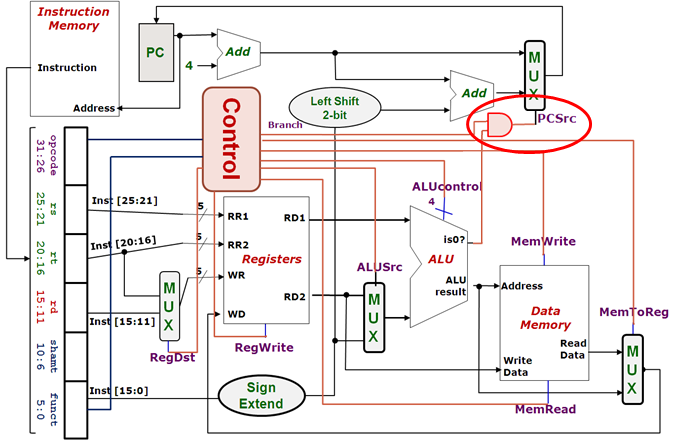
Wait, but PCSrc depends on the result of comparison from isZero?.
- False (
0): The operation is not a branch operation - True (
1): The operation is a branch operation (i.e.,beq)
PCSrc = Branch & isZero?
Now we are left only with the ALUcontrol signal.
-
We cannot have
MemReadandMemWriteboth to have a value of1. Therefore, there are only 3 possible values for the combination ofMemReadandMemWrite:00,01and10. ↩↩ -
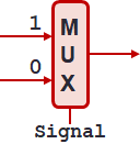
If you notice, the multiplexer is flipped! Control value
0choose from the bottom while control value1choose from the top input line. ↩ -
This is sometime written as
PCSrc. But note thatPCSrcis often refer toBranch & isZero?instead. ↩