Control Unit
We have now considered all individual signal and their expected values. We are now ready to design the control unit itself. The derivation of the ALU control unit illustrates the typical steps in digital design:
- Fill in truth table.
- Derive simplified expression for each signal.
We will use the same technique to derive all of the control signal used by the processor with the exception of ALUcontrol.
Truth Table
The expected outputs are shown below.
| RegDst | ALUSrc | MemToReg | RegWrite | MemRead | MemWrite | Branch | ALUop1 | ALUop0 | |
|---|---|---|---|---|---|---|---|---|---|
| R-Format | 1 |
0 |
0 |
1 |
0 |
0 |
0 |
1 |
0 |
lw |
0 |
1 |
1 |
1 |
1 |
0 |
0 |
0 |
0 |
sw |
X |
1 |
X |
0 |
0 |
1 |
0 |
0 |
0 |
beq |
X |
0 |
X |
0 |
0 |
0 |
1 |
0 |
1 |
For simplicity, we will merge them all based on the position.
We will simply call them Ctrl signal.
So, Ctrl2 is really just MemToReg.
The expected inputs are shown below.
Here we use Op0 to Op5 to mean the bit 0 to bit 5 of the opcode.
| Op5 | Op4 | Op3 | Op2 | Op1 | Op0 | Hexadecimal | |
|---|---|---|---|---|---|---|---|
| R-Format | 0 |
0 |
0 |
0 |
0 |
0 |
0 |
lw |
1 |
0 |
0 |
0 |
1 |
1 |
23 |
sw |
1 |
0 |
1 |
0 |
1 |
1 |
2B |
beq |
0 |
0 |
0 |
1 |
0 |
0 |
4 |
The truth table is then constructed by merging the inputs with the outputs.
opcode |
Ctrl | |
|---|---|---|
| R-Format | 0 0 0 0 0 0 | 1 0 0 1 0 0 0 1 0 |
lw |
1 0 0 0 1 1 | 0 1 1 1 1 0 0 0 0 |
sw |
1 0 1 0 1 1 | X 1 X 0 0 1 0 0 0 |
beq |
0 0 0 1 0 0 | X 0 X 0 0 0 1 0 1 |
Implementation
Now, we can try to deduce the operations that we can use to produce each bit of the Ctrl.
Here, we can use the X value to our advantage because it does matter what we actually produce as the output, we will automatically satisfy that output.
With that in mind, we can now try to simplify the output logically by looking at the instruction rather than individual bits of the opcode.
For instance, we can say that Ctrl0 (i.e., RegDst) is 1 if the operation is R-format.
Note that we do not care what the value of X will be by choosing this.
With that, we can first simplify each operation as follows:
| Ctrl | Signal | Selector |
|---|---|---|
| 0 | RegDst |
R-Format |
| 1 | ALUSrc |
lw OR sw |
| 2 | MemToReg |
lw |
| 3 | RegWrite |
R-Format OR lw |
| 4 | MemRead |
lw |
| 5 | MemWrite |
sw |
| 6 | Branch |
beq |
| 7 | ALUop1 |
R-Format |
| 8 | ALUop0 |
beq |
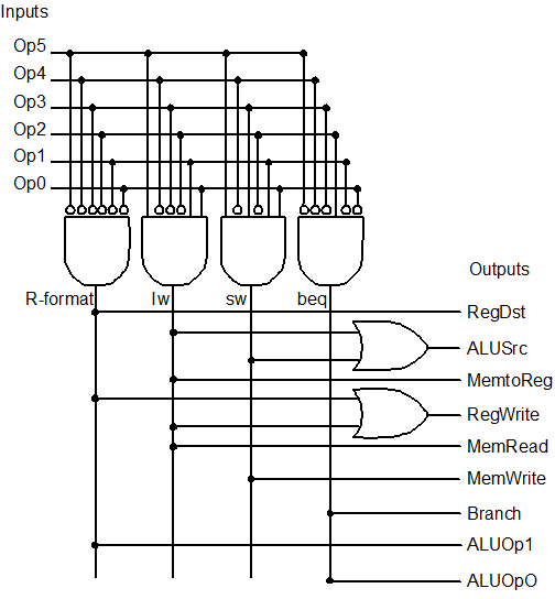
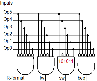
What is nice about this is that the selector only uses bitwise OR. But how do we know if we are currently executing a particular instruction? For instance, how do we know if we are executing R-format instruction?
The simplest way is to simply look at the input and say that it is R-format if all the input is all 0. How do we know that all input is all 0 then? Well, we negate all the inputs (i.e., put all the input through NOT gate) and then pass all negated inputs through AND gate.
In fact, this way leads to a systematic way of determining any selector by simply looking at its characteristic input. Then, for each bit 0, we pass it through a NOT gate. Otherwise, we simply use it as it is. Now, by passing all the preprocessed inputs into an AND gate, the output is 1 if and only if it is the given selector.
Okay, that might be too abstract. But the implementation is really just the following for the selector.
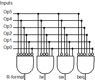
Now here is the nice thing, if you look at the input, the bubble there is a "collapsed" NOT gate.
The NOT gate is practically just the bubble.
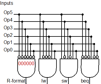
The other nice thing is that the bubble looks like 0.
So, if you want to read it, R-format is 1 if all inputs are 0.
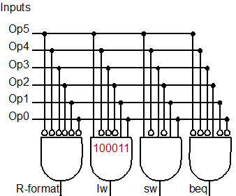
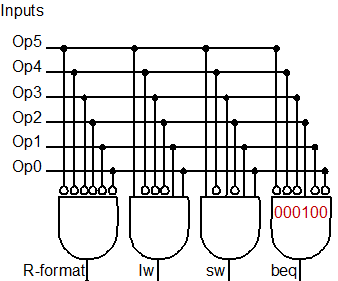
Similarly, lw is 1 if the input is specifically 100010.
Explanation
So now, we have managed to get the selector. The final step is to combine the selector using the OR gate appropriately to give us the following implementation.