ALU Control
We will take a closer look at the ALU.
The ALU itself is actually a combinational circuit that is capable of performing several arithmetic operations.
Combinational circuit has no internal state, so the output is dependent purely on the inputs.
In this case, we will have to include the ALUcontrol signal as part of the input to the ALU.
ALUcontrol
| ALUcontrol | Function |
|---|---|
| 0000 | and |
| 0001 | or |
| 0010 | add |
| 0110 | sub |
| 0111 | slt |
| 1100 | nor |
Combinational Circuit
We will cover combinational circuits in the second half of the semester.
For now, simply remember that the current draft (i.e., v0.5) is as follows:
ALU
We will create the ALU one bit at a time. So we will consider an ALU that will perform operations on only 1-bit data.
1-Bit ALU
A simplified 1-bit MIPS ALU can be implemented as follows1:
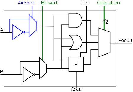
There are 4 control bits needed:
-
Ainvert(1-bit)0: Do not invert inputA1: Invert inputA
-
Binvert(1-bit)0: Do not invert inputB1: Invert inputB
-
Operation(2-bits)00: Result of bitwise AND01: Result of bitwise OR10: Result of ADD
Elements
There are different elements in the 1-bit ALU. While you will be learning them at the second half of the semester, we will show some of them here using the functional conceptual view. Since we are dealing with boolean, we will be

| NOT Gate | |
|---|---|
1 2 3 | |

| AND Gate | |
|---|---|
1 2 3 | |

| OR Gate | |
|---|---|
1 2 3 | |

| Adder | |
|---|---|
1 2 3 | |
This element is basically add 3 bit values. One of the value is a carry bit from previous addition. There are two outputs, the result of the summation for the particular bit and the resulting carry bit to be used by the next addition.

| Multiplexer | |
|---|---|
1 2 3 4 5 6 7 | |
Similar to multiplexer but different symbol. We simply select the correct input to return.
Now, we can see how the 4-bits ALUcontrol signal is created.
Note that the implementation for slt is not shown.
| Function | Ainvert | Binvert | Operation | ALUcontrol |
|---|---|---|---|---|
and |
0 | 0 | 00 | 0000 |
or |
0 | 0 | 01 | 0001 |
add |
0 | 0 | 10 | 0010 |
sub |
0 | 1 | 10 | 0110 |
slt |
0 | 1 | 11 | 0111 |
nor |
1 | 1 | 00 | 1100 |
Now we can start to design the ALUcontrol signal.
This signal must depend on:
opcode:Inst[26:31]funct:Inst[0:5]
There are multiple ways we can do this.
Brute Force
The most obvious way to do this is to brute force our way.
This can be done by finding a function that takes in two inputs, the opcode and funct (e.g., ctrl_regdst(opcode, funct)).
In principle, this will be like finding expressions with 12 variables (i.e., 6-bits opcode and 6-bits funct).
Multilevel Decoding
The second approach is to use some of the input to reduce the cases. We can then generate the full output from this reduced cases. This will simplify the design process, reduce the size of the main controller and potentially speedup the circuit. As such, this will be our preferred approach.
32-Bit ALU
A simplified 1-bit MIPS ALU can be abstracted further by ignoring the internals.
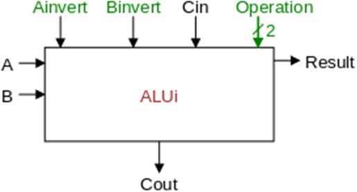
Given this, we can then connect Cout output from 1-bit to Cin input for another 1-bit.
This lets us add any 32-bits number.
By chaining all of the results, we can then get the following 32-bit ALU.
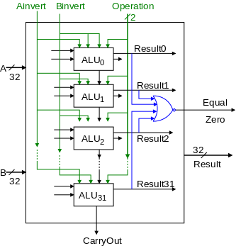
And voila! We have just created the 32-bit ALU.
This assumes that we can generate the ALUcontrol, which we will do next.
Multilevel Decoding
Using multilevel decoding approach, we can try to generate an intermediate signal.
This intermediate signal is again simply a convention but what is important is that it can only depend on opcode.
In other words, we can always have other conventions and proceed from there.
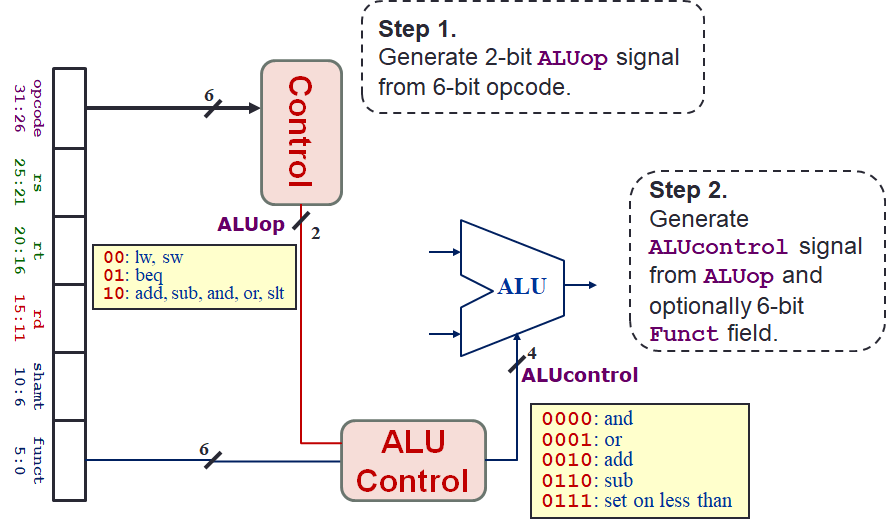
Our convention is a 2-bit ALUop signal which is as follows:
| Instruction Type | ALUop |
|---|---|
lw/sw |
00 |
beq |
01 |
| R-Format | 10 |
Quick Quiz
Why is it useful to differentiate the ALUop into 3 different values as above?
One possible reason is because of the type of operations performed by the ALU.
Consider both lw and sw.
These two operations are performing addition to compute the address (i.e., base + offset).
On the other hand, beq is performing subtraction since two values are equal if their difference is 0.
Lastly, R-format instruction may do a lot of other things but since we are simply looking at the opcode, we cannot differentiate what it will need to do.
So, we defer this decision until we are looking at the funct field and simply mark this as something like "other".
This ALUop signal can be generated fully from the opcode.
Then, using this 2-bit ALUop signal and the 6-bit funct field for the R-format instructions, we will generate the 4-bit ALUcontrol signal.
Now we are ready to generate the ALUcontrol signal.
We will discuss how to generate the ALUop signal later together with the rest of the other control signals.
But we have achieved part of our objective to reduce the complexity of generating ALUcontrol.
Summary Table
We can first construct a summary table. From this, we can generate the truth table. Using the truth table, we can hopefully find a pattern. But first, let us put the ground rule and convention to be used.
- We use
1to indicatetrueand0to indicatefalse. - We use
Xto indicate that the value can be either1or0- If
Xappears in the output, then it does not matter what the value is. - If
Xappears in the input, then we have to ensure that the operation works regardless of what the value is.
- If
- We can only use the following operations:
- Bitwise OR: Indicate by
+. - Bitwise AND: Indicate by
.. - Bitwise NOT: Indicate by
!or~.
- Bitwise OR: Indicate by
| Opcode | ALUop | Instruction | Funct | Action | ALUcontrol |
|---|---|---|---|---|---|
lw |
00 |
Load | XX XXXX |
Add | 0010 |
sw |
00 |
Store | XX XXXX |
Add | 0010 |
beq |
01 |
Branch | XX XXXX |
Subtract | 0110 |
| R-Format | 10 |
Add | 10 0000 |
Add | 0010 |
| R-Format | 10 |
Subtract | 10 0010 |
Subtract | 0110 |
| R-Format | 10 |
AND | 10 0100 |
AND | 0000 |
| R-Format | 10 |
OR | 10 0101 |
OR | 0001 |
| R-Format | 10 |
Less Than | 10 1010 |
Less Than | 0111 |
Truth Table
So now, we can construct the truth table.
The inputs are the ALUop signal and funct field.
Since the funct field are 6-bit wide, we can number them for easy identification.
We will use the name F0 to F5 to mean the bit from funct field at index 0 to 5 respectively.
Similarly, we will use ALUop0 and ALUop1 to mean the bit from ALUop signal at index 0 and 1 respectively.
Finally, we will use ALUcontrol0 to ALUcontrol3 to mean the bit from ALUcontrol signal at index 0 to 3 respectively.
| ALUop | Funct | ALUcontrol | |
|---|---|---|---|
lw |
0 0 |
X X X X X X |
0 0 1 0 |
sw |
0 0 |
X X X X X X |
0 0 1 0 |
beq |
0 1 |
X X X X X X |
0 1 1 0 |
add |
1 0 |
1 0 0 0 0 0 |
0 0 1 0 |
sub |
1 0 |
1 0 0 0 1 0 |
0 1 1 0 |
and |
1 0 |
1 0 0 1 0 0 |
0 0 0 0 |
or |
1 0 |
1 0 0 1 0 1 |
0 0 0 1 |
slt |
1 0 |
1 0 1 0 1 0 |
0 1 1 1 |
So, the idea of constructing the operations to solve for this is to find pattern.
To do that, we can try to simplify the pattern.
Sometimes, we may be able to ignore the input since they definitely cannot depend on that.
In such cases, maybe it is simpler to just ignore it and replace with - because the output is guaranteed to work regardless of that value.
Note that it is not X which is a don't care (i.e., can be either 0 or 1).
Simplification
| ALUop | Funct | ALUcontrol | |
|---|---|---|---|
lw |
0 0 |
X X X X X X |
0 0 1 0 |
sw |
0 0 |
X X X X X X |
0 0 1 0 |
beq |
0 1 |
X X X X X X |
0 1 1 0 |
add |
1 0 |
- - 0 0 0 0 |
0 0 1 0 |
sub |
1 0 |
- - 0 0 1 0 |
0 1 1 0 |
and |
1 0 |
- - 0 1 0 0 |
0 0 0 0 |
or |
1 0 |
- - 0 1 0 1 |
0 0 0 1 |
slt |
1 0 |
- - 1 0 1 0 |
0 1 1 1 |
We can ignore F5 and F4 because these values are all the same for any R-format.
As such, we cannot use this to differentiate any output.
| ALUop | Funct | ALUcontrol | |
|---|---|---|---|
lw |
0 0 |
X X X X X X |
0 0 1 0 |
sw |
0 0 |
X X X X X X |
0 0 1 0 |
beq |
0 1 |
X X X X X X |
0 1 1 0 |
add |
1 - |
- - 0 0 0 0 |
0 0 1 0 |
sub |
1 - |
- - 0 0 1 0 |
0 1 1 0 |
and |
1 - |
- - 0 1 0 0 |
0 0 0 0 |
or |
1 - |
- - 0 1 0 1 |
0 0 0 1 |
slt |
1 - |
- - 1 0 1 0 |
0 1 1 1 |
Similar reasoning as "Step 1".
At this point, it is good to note that we can differentiate R-format instructions with the rest using ALUop1.
| ALUop | Funct | ALUcontrol | |
|---|---|---|---|
lw |
0 0 |
X X X X X X |
0 0 1 0 |
sw |
0 0 |
X X X X X X |
0 0 1 0 |
beq |
- 1 |
X X X X X X |
0 1 1 0 |
add |
1 - |
- - 0 0 0 0 |
0 0 1 0 |
sub |
1 - |
- - 0 0 1 0 |
0 1 1 0 |
and |
1 - |
- - 0 1 0 0 |
0 0 0 0 |
or |
1 - |
- - 0 1 0 1 |
0 0 0 1 |
slt |
1 - |
- - 1 0 1 0 |
0 1 1 1 |
Since we can differentiate R-format from the rest using ALUop1, we can now differentiate beq from both lw and sw using only ALUop0.
Simplfied Truth Table
So now we arrived at the simplified truth table below.
| ALUop | Funct | ALUcontrol | |
|---|---|---|---|
lw |
0 0 | X X X X X X | 0 0 1 0 |
sw |
0 0 | X X X X X X | 0 0 1 0 |
beq |
- 1 | X X X X X X | 0 1 1 0 |
add |
1 - | - - 0 0 0 0 | 0 0 1 0 |
sub |
1 - | - - 0 0 1 0 | 0 1 1 0 |
and |
1 - | - - 0 1 0 0 | 0 0 0 0 |
or |
1 - | - - 0 1 0 1 | 0 0 0 1 |
slt |
1 - | - - 1 0 1 0 | 0 1 1 1 |
Using this simplified truth table, we are ready to deduce the operat-ons to generate ALUcontrol.
ALuControl3
First note that ALUcontrol3 is always 0.
| ALUop | Funct | ALUcontrol | |
|---|---|---|---|
lw |
0 0 | X X X X X X | 0 0 1 0 |
sw |
0 0 | X X X X X X | 0 0 1 0 |
beq |
- 1 | X X X X X X | 0 1 1 0 |
add |
1 - | - - 0 0 0 0 | 0 0 1 0 |
sub |
1 - | - - 0 0 1 0 | 0 1 1 0 |
and |
1 - | - - 0 1 0 0 | 0 0 0 0 |
or |
1 - | - - 0 1 0 1 | 0 0 0 1 |
slt |
1 - | - - 1 0 1 0 | 0 1 1 1 |
ALUcontrol3
ALUcontrol3 = 0
ALUcontrol2
Second, note that for ALUcontrol2, the value where it is 1 lines up nicely with F1.
But this is only true if the instruction is R-format instruction.
| ALUop | Funct | ALUcontrol | |
|---|---|---|---|
lw |
0 0 | X X X X X X | 0 0 1 0 |
sw |
0 0 | X X X X X X | 0 0 1 0 |
beq |
- 1 | X X X X X X | 0 1 1 0 |
add |
1 - | - - 0 0 0 0 | 0 0 1 0 |
sub |
1 - | - - 0 0 1 0 | 0 1 1 0 |
and |
1 - | - - 0 1 0 0 | 0 0 0 0 |
or |
1 - | - - 0 1 0 1 | 0 0 0 1 |
slt |
1 - | - - 1 0 1 0 | 0 1 1 1 |
We can say that:
ALUcontrol2is 1 ifF1is 1 ANDALUop1is 1 (i.e., R-format)
This gives us one part of the solution: F1 . ALUop1.
Now, if the instruction is NOT R-format, then ALUcontrol2 is 1 if the operation is beq.
We can identify if it is beq by ALUop0.
| ALUop | Funct | ALUcontrol | |
|---|---|---|---|
lw |
0 0 | X X X X X X | 0 0 1 0 |
sw |
0 0 | X X X X X X | 0 0 1 0 |
beq |
- 1 | X X X X X X | 0 1 1 0 |
add |
1 - | - - 0 0 0 0 | 0 0 1 0 |
sub |
1 - | - - 0 0 1 0 | 0 1 1 0 |
and |
1 - | - - 0 1 0 0 | 0 0 0 0 |
or |
1 - | - - 0 1 0 1 | 0 0 0 1 |
slt |
1 - | - - 1 0 1 0 | 0 1 1 1 |
We can say that:
ALUcontrol2is 1 ifALUop0is 1 (i.e.,beq).
This gives us the other part of the solution: ALUop0.
Combining the two, we can say that it is 1 if either one or both of the above is true.
ALUcontrol2
ALUcontrol2 = (F1 . ALUop1) + (ALUop0)
ALUcontrol1
Using similar method as before, note that ALUcontrol1 is 0 if F2 is 1 and the instruction is R-format.
| ALUop | Funct | ALUcontrol | |
|---|---|---|---|
lw |
0 0 | X X X X X X | 0 0 1 0 |
sw |
0 0 | X X X X X X | 0 0 1 0 |
beq |
- 1 | X X X X X X | 0 1 1 0 |
add |
1 - | - - 0 0 0 0 | 0 0 1 0 |
sub |
1 - | - - 0 0 1 0 | 0 1 1 0 |
and |
1 - | - - 0 1 0 0 | 0 0 0 0 |
or |
1 - | - - 0 1 0 1 | 0 0 0 1 |
slt |
1 - | - - 1 0 1 0 | 0 1 1 1 |
ALUcontrol1 = ALUop1 . !F2
On the other hand, for non R-format, we simply set it to 1.
| ALUop | Funct | ALUcontrol | |
|---|---|---|---|
lw |
0 0 | X X X X X X | 0 0 1 0 |
sw |
0 0 | X X X X X X | 0 0 1 0 |
beq |
- 1 | X X X X X X | 0 1 1 0 |
add |
1 - | - - 0 0 0 0 | 0 0 1 0 |
sub |
1 - | - - 0 0 1 0 | 0 1 1 0 |
and |
1 - | - - 0 1 0 0 | 0 0 0 0 |
or |
1 - | - - 0 1 0 1 | 0 0 0 1 |
slt |
1 - | - - 1 0 1 0 | 0 1 1 1 |
ALUcontrol1 = !ALUop1
We can then combine as before to get:
ALUcontrol1 v1
ALUcontrol1 = (ALUop1 . !F2) + (!ALUop1)
You can try to simplify this, but we do not have the technique yet, that will only be available later. However, we can take a look at the overall pattern and note that:
ALUcontrol1is 0 ifALUop1is 1 andF2is 1.
But since we are interested in the point where they are 1, we can negate this entire condition.
ALUcontrol1 = !(ALUop1 . F2)
But using De Morgan's Law, this is simply:
ALUcontrol1 = !ALUop1 + !F2
ALUcontrol1
ALUcontrol1 = !ALUop1 + !F2
ALUcontrol0
Lastly, for ALUcontrol0, we simply note that the formula will be as follows.
Can you figure out how to deduce that?
ALUcontrol0
ALUcontrol0 = (F0 + F3) . ALUop1
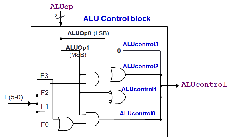
ALU Control Unit
Let us first summarise the formula for each ALUcontrol bit.
| ALUcontrol | |
|---|---|
1 2 3 4 | |
This gives us the following circuit.
-
Image taken from NYU Course CSCI-UA.0436 ↩