From C to Execution
Summary
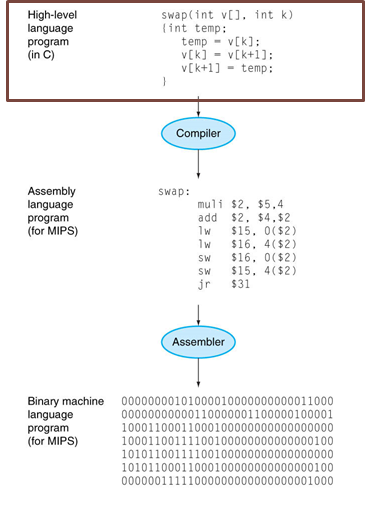
We first write a program in high-level language (e.g., C).
| High-Level | |
|---|---|
1 2 3 | |
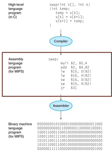
Compiler translates to assembly language (e.g., MIPS).
| Assembly | |
|---|---|
1 2 3 4 5 | |
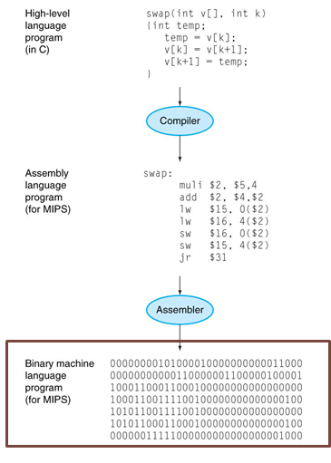
Assembler translates to machine language (i.e., binaries).
| Assembly | |
|---|---|
1 2 3 4 | |
Immediate Values?
| Assembly | |
|---|---|
1 2 3 4 | |

Processor executes the machine code (i.e., binaries).
We will play the role of programmer, compiler, assembler and processor.
- Programmer: Show the workflow of compiling, assembling and executing C program.
- Compiler: Show how the program is compiled into MIPS (tools | slides).
- Assembler: Show how the MIPS is translated into binaries (tools | slides).
- Processor: Show how the datapath is activated in the processor (tools | slides).
Our program is the same as above, reproduced below.
| sample.c | |
|---|---|
1 2 3 | |
Programmer
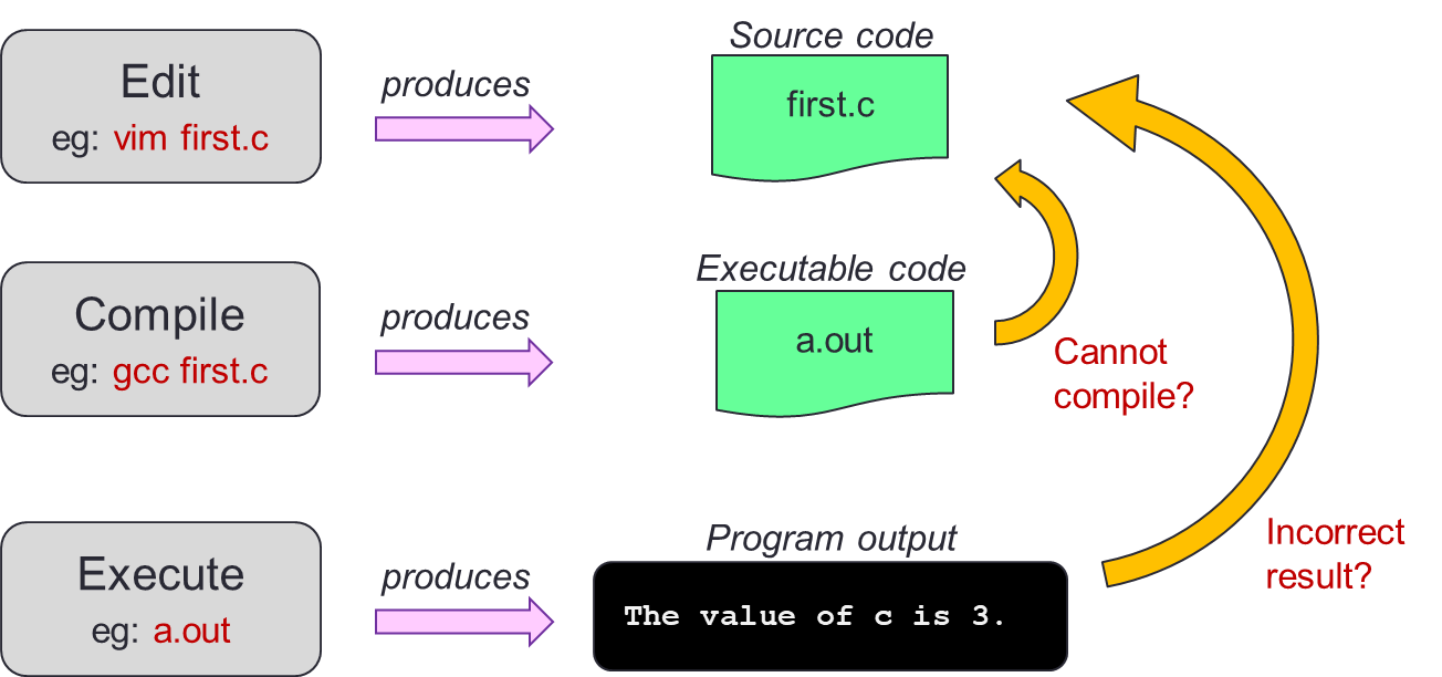
As a programmer, we typically concern only about the writing programs using high-level language. Later on in the semester, you will learn how certain access pattern may actually improve (or reduce) the performance of your program drastically. The main workflow that we are interested in as a programmer is the Edit, Compile, Execute workflow.
Steps
-
Create a new C program file (with the extension
.c) or edit an existing one.- We would recommend the use of
vim(orviimproved) as it is available in all UNIX system like sunfire.
- We would recommend the use of
-
Save the file (e.g.,
sample.c).
- Compile your C program file from "Edit" step using GCC (e.g.,
gcc sample.c). - You will either:
- Produce an executable code (e.g.,
a.out) then you continue to "Execute" step. - Fail to compile (i.e., compile error) then you repeat "Edit" step to repair the program and remove the compile error.
- Produce an executable code (e.g.,
- Execute your executable (e.g.,
a.outor./a.out). - You will either:
- Get the correct program output and you are satisfied with your work and finish.
- Get the incorrect program output then you repeat "Edit" and "Compile" step to repair the program until you get the correct program output.
Compiler
Now that we have our program, we can start compiling this program into MIPS.
We will highlight key ideas in compilation.
Although we will use the specific example of sample.c, we hope that the key ideas are applicable to other programs.
Key Ideas
Key Idea #1
Compilation is a structured process. In particular, each structure can be compiled independently.
In the case of the program in sample.c, we can identify two structures.
| Inner Structure | |
|---|---|
1 2 3 4 5 | |
| Outer Structure | |
|---|---|
1 2 3 4 5 | |
If you combine structures, you will then get the original program:
| Full Structure | |
|---|---|
1 2 3 4 5 | |
| Full Structure | |
|---|---|
1 2 3 4 5 | |
| Full Structure | |
|---|---|
1 2 3 4 5 | |
We will highlight certain common structures in high-level programming languages.
You will notice that they match nicely to the syntax of the program.
You may want to try finding the structures for other programming languages.
The structures will be marked with <structure name>.
Common Structures
| If-Else | |
|---|---|
1 2 3 4 5 | |
| While Loop | |
|---|---|
1 2 3 | |
| While Loop | |
|---|---|
1 2 3 | |
| While Loop | |
|---|---|
1 2 3 | |
Key Idea #2
Variables are mapped to register.
Consider our sample program again.
We can identify two variables: a and x.
We then have to find a mapping for these two variables.
Remember that not all registers are available.
Additionally, there are "conventional usage" but that is simply a convention.
Your assembly code will still work, but might be less intuitive to read.
Using the convention, "program variables" should use the registers in the range of $s0 - $s7.
We can consider the following mapping:
| Variable | Register | Number |
|---|---|---|
x |
$s0 |
$16 |
&a[0] |
$s1 |
$17 |
Common Techniques
Common Technique #1
Invert the condition for shorter code.
This common technique works for if-statement but may not provide benefit for if-else-statement. Additionally, this is a common technique for while-loop and for-loop but may not be useful for do-while-loop.
Why?
In the case of if-else-statemenet, we have both branches available. So the technique provide no benefit. As for do-while-loop, we are repeating by branching back to the top when the condition is still satisfied. This match nicely with the semantics of do-while-loop without inversion.
Consider the inner structure again. We can compile this using the inversion technique as follows:
| Outer Structure | |
|---|---|
1 2 3 4 5 | |
| Outer MIPS | |
|---|---|
1 2 3 4 5 | |
Common Technique #2
Break complex operations and use temporary registers to store the intermediate result.
This is where using convention is useful.
If we have kept registers $t0 - $t9 free, we can use these registers during our compilation without worrying whether it will break other parts of the program or not1.
| Inner Structure | |
|---|---|
1 2 3 4 5 | |
| Simplified Inner | |
|---|---|
1 2 3 4 5 | |
Common Technique #3
Array access is lw, array update is sw and the offset depends on the type.
| Simplified Inner | |
|---|---|
1 2 3 4 5 | |
| Inner MIPS | |
|---|---|
1 2 3 4 5 | |
Common Error
Note that common technique #3 mentions that the offset depends on the type. The most common error is to assume that the address of the next word can be found by incrementing the address in a register by 1. This is wrong because we have to increment it by the word size in bytes. The principle used here is word-alignment.
Now the last step is to combine the inner MIPS with the outer MIPS to produce the full MIPS.
| Inner MIPS | |
|---|---|
1 2 3 4 5 | |
| Outer MIPS | |
|---|---|
1 2 3 4 5 | |
This combined structure yield the compiled version of sample.c.
| Full MIPS | |
|---|---|
1 2 3 4 5 | |
| Full MIPS | |
|---|---|
1 2 3 4 5 | |
| Full MIPS | |
|---|---|
1 2 3 4 5 | |
Assembler
There are two main steps to perform the assembly.
-
Label Removal
- Convert label to immediate constant.
-
Binary Conversion
- Find the instruction formats: R-format, I-format or J-format.
- For each field in the format, fill in the value in decimal/hexadecimal.
- Since the labels are gone, we can fill in the immediate values.
- Convert to binary.
- You may combine this step with the previous one if you already prepared all values in binaries.
Label Removal
| With Label | |
|---|---|
1 2 3 4 5 | |
| Without Label | |
|---|---|
1 2 3 4 5 | |
How do we remove the label? There are two ways, the first is the equational method (i.e., formulaic method by solving a certain equation) and the second is the diagrammatic method. Both are illustrated below. Note that the equational method abstracted the current address as you will see later that it will nicely cancel out due to the formula.
Immediate Conversion
The current $PC is X.
The target address $PC' is X+16.
We need to solve the equation $PC' = ($PC + 4) + (immediate × 4) given that we know the value of $PC and $PC'.
| Computation of Immediate | |
|---|---|
1 2 3 4 5 6 | |
So, the value of immediate field should be 3.
-
Draw a line below the current instruction (this represents the
$PC + 4).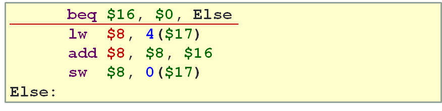
-
Draw a line above the target instruction (this represents the
$PC').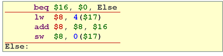
-
Complete the box.
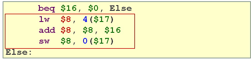
-
Count the number of instructions within the box (this represents the
immediate × 4).- If the target label is after, keep the value as positive.
- If the target label is before, convert the value to negative.
Similar to the previous method, we get the answer for the immediate field as 3.
Binary Conversion
So now we can start from the intermediate assembly code without label.
| Intermediate MIPS | |
|---|---|
1 2 3 4 | |
The steps are laid down below.
| Intermediate MIPS | |
|---|---|
1 2 3 4 | |
-
- Format: I-Format
-
Fields:
Fields Decimal Value Binaries opcode4 000100 $rs16 10000 $rt0 00000 immediate3 0000000000000011
Code:
beq $16, $0, 3- Binary: 00010010000000000000000000000011
| Intermediate MIPS | |
|---|---|
1 2 3 4 | |
-
- Format: I-Format
-
Fields:
Fields Decimal Value Binaries opcode35 100011 $rs17 10001 $rt8 01000 immediate4 0000000000000100
Code:
lw $8 , 4($17)- Binary: 10001110001010000000000000000100
| Intermediate MIPS | |
|---|---|
1 2 3 4 | |
-
- Format: R-Format
-
Fields:
Fields Decimal Value Binaries opcode0 000000 $rs8 01000 $rt16 10000 $rd8 01000 shamt0 00000 funct32 100000
Code:
add $8 , $8, $16- Binary: 00000001000100000100000000100000
| Intermediate MIPS | |
|---|---|
1 2 3 4 | |
-
- Format: R-Format
-
Fields:
Fields Decimal Value Binaries opcode43 101011 $rs17 10001 $rt8 01000 immediate0 0000000000000000
Code:
sw $8 , 0($17)- Binary: 10101110001010000000000000000000
| Binary | |
|---|---|
1 2 3 4 | |
| Hexadecimal | |
|---|---|
1 2 3 4 | |
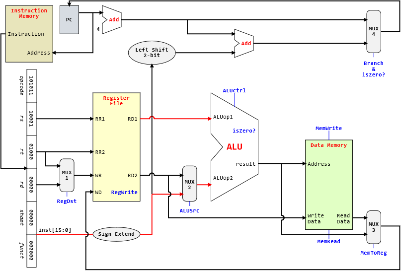
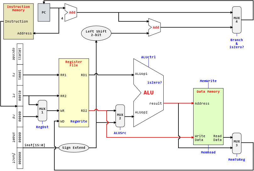
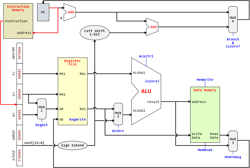
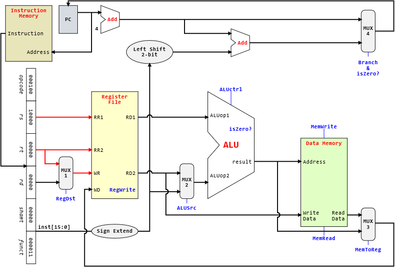
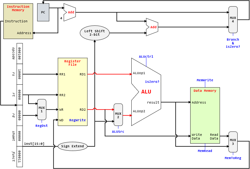
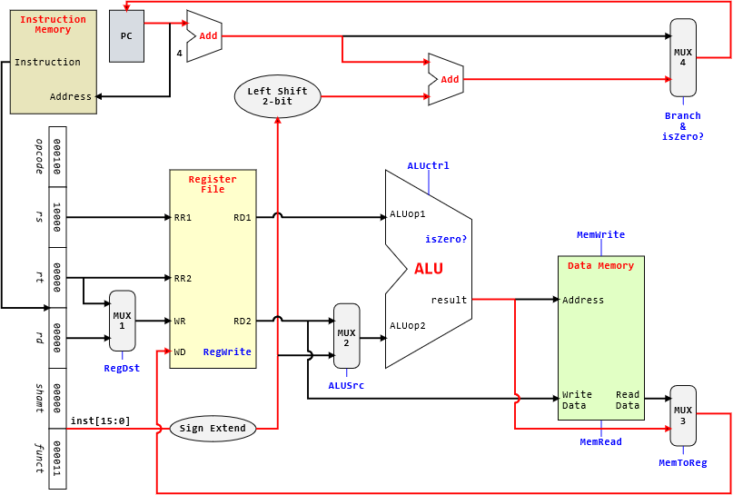
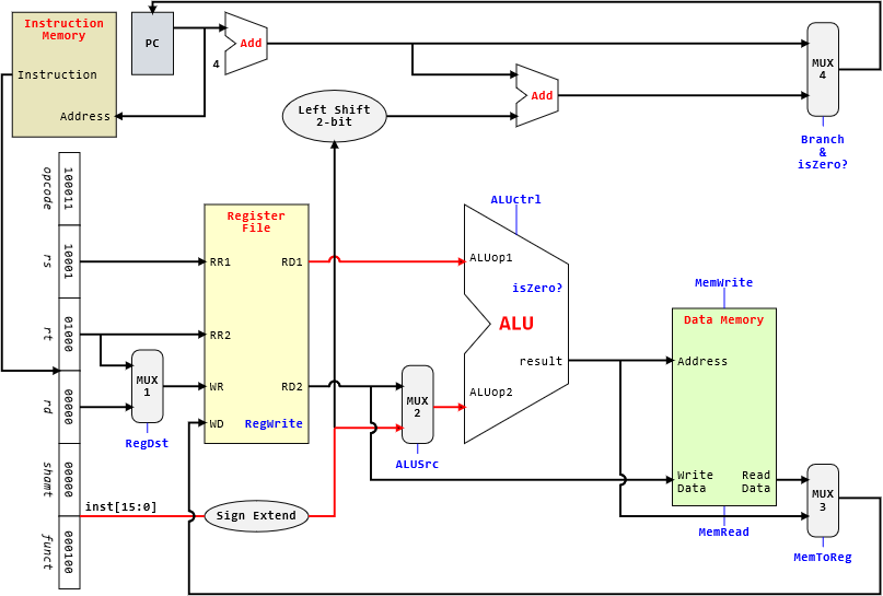
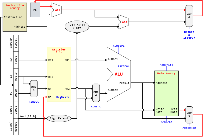
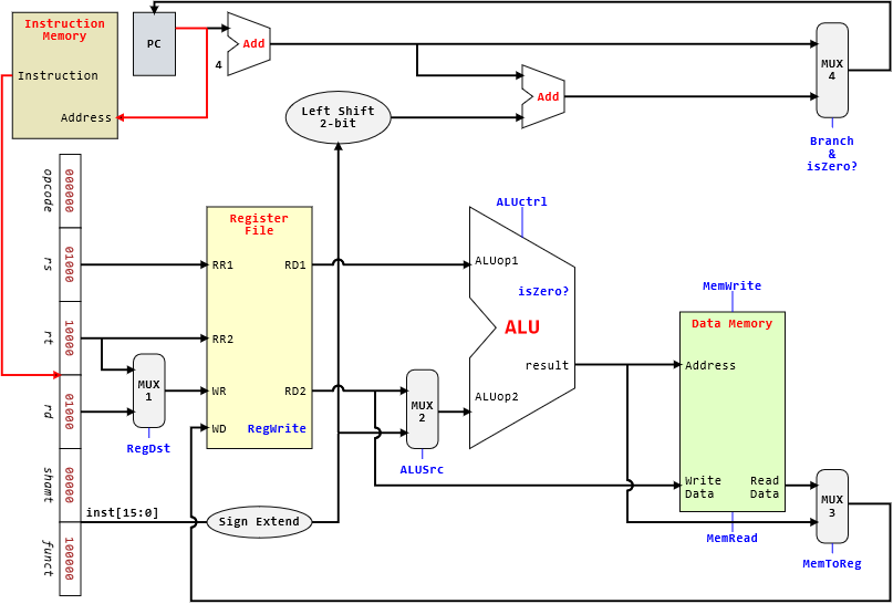
Processor
Once we have the machine code, we can let the processor to run the code. Typically the machine code is written in hexadecimal for human to read, but it is given to processor in binary to execute. Note that when we say it is in binary, it is truly in binary and not textual representation of binary.
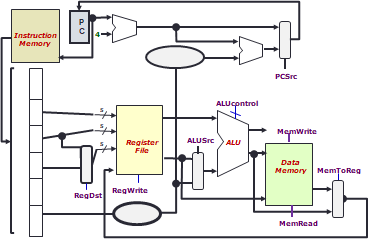
So let us try to put ourselves as a processor and look at the execution of the program looking mainly at the datapath for the 5 stages.
We put the update of $PC in the writeback stage instead of ALU stage.
However, we will still be simulating the control signal to show you which inputs are selected by multiplexers, which operations are performed by the ALU, etc.
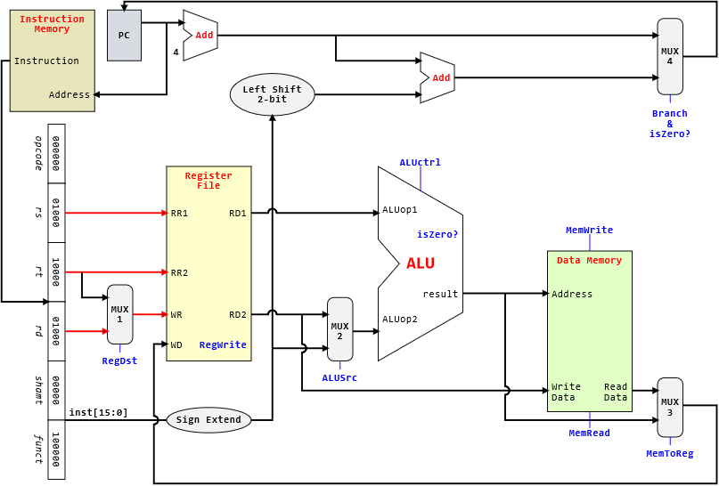
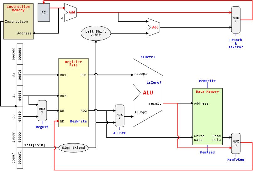
Lastly, note that there are two possible execution of the program:
- When the content of register
$16is equal to the content of register$0. - When the content of register
$16is not equal to the content of register$0.
| Binary | |
|---|---|
1 2 3 4 | |

| Binary | |
|---|---|
1 2 3 4 | |

| Binary | |
|---|---|
1 2 3 4 | |


| Binary | |
|---|---|
1 2 3 4 | |


| Binary | |
|---|---|
1 2 3 4 | |